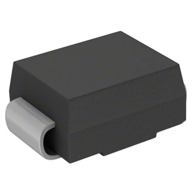
Surge clamp for a 24 V DC bus
The 1.5SMC27CA_R1_00001: Its 23.1 V reverse standoff voltage sits below the rail's steady-state tolerance, so it stays out of conduction during normal operation, but triggers when a surge pushes the line above its 25.7 V minimum breakdown threshold.
What the clamping numbers mean for your rail
The 23.1 V reverse standoff is the maximum DC or peak AC voltage the TVS can see without conducting appreciable leakage. For a 24 V bus that sags to 22 V and rises to 26 V under load transients, this part stays dark — the breakdown window starts at 25.7 V, so a 26 V transient just kisses the knee and the TVS begins to steer current. At the full 40 A peak pulse current, the clamp voltage hits 37.5 V max. That is the ceiling the downstream circuitry must tolerate — a 30 V-rated capacitor on the bus sees a 7.5 V margin above its rating, which is tight. The designer should verify the downstream components' avalanche or derating curves against this clamp level.
Housed in a DO-214AB (SMC) package, the part's footprint matches the supplier device package designation — the same copper pad area used for the cathode tab on unidirectional versions. The bidirectional variant has no polarity marking on the body, so the pick-and-place orientation is arbitrary. Surface mount assembly with a tape-and-reel or cut-tape option — the reel quantity is set by the manufacturer's standard packaging, and the part is MSL-rated per JEDEC for the SMC body size.
It is available for new designs and ongoing production.