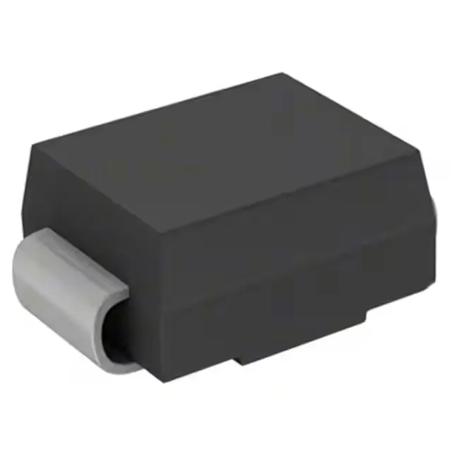
1.5 kW peak pulse rating and clamping performance
The 1.5SMC130A_R1_00001: The 111 V reverse standoff voltage means the protected rail can run at 111 V DC without the diode conducting leakage current — the breakdown threshold starts at 124 V minimum, giving a 13 V guard band before the avalanche region. The 179 V clamping ceiling at 8.4 A Ipp defines the voltage the downstream circuitry sees during a surge event. For a 111 V nominal bus, this clamp margin of roughly 68 V above standoff is typical for a 1.5 kW device in this package — the DO-214AB body dissipates the pulse energy without exceeding the 150 °C junction limit across the -55 to +150 °C operating range.
DO-214AB SMC package and board integration
Housed in the standard DO-214AB (SMC) surface-mount package, the 1.5SMC130A_R1_00001 mounts directly to the PCB copper pad — the cathode tab on the SMC body carries the bulk of the thermal path to the board. The junction-to-ambient thermal resistance depends on the pad area; a 645 mm² copper land per JEDEC JESD51-7 keeps the junction temperature rise within the 150 °C absolute maximum during repetitive pulse trains. The SMC footprint is shared across the 1.5SMC series, so a single PCB layout serves the full voltage range from 6.8 V to 220 V standoff — useful when a BOM carries multiple rail voltages protected by the same package family.