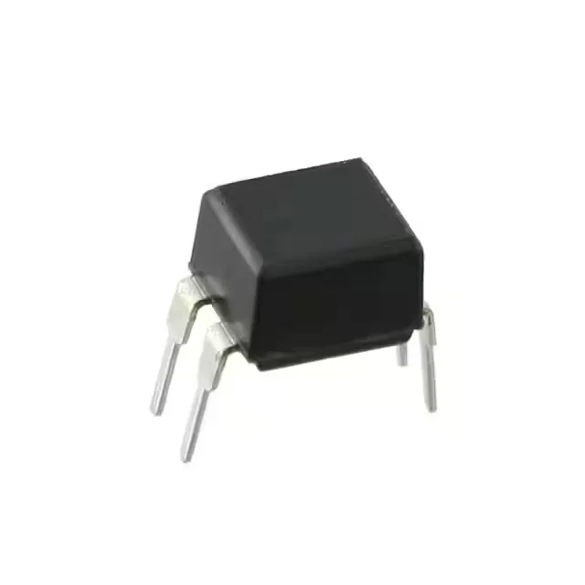
Isolation barrier and signal transfer
The H11A817A: Rated for 5300 Vrms isolation — this is the withstand voltage between the LED input and the phototransistor output, tested per the device's safety standard. For a mains-referenced circuit requiring reinforced isolation, this rating provides the barrier margin needed to pass the production hipot test. Current transfer ratio spans 80% to 160% at a forward current of 5 mA — the minimum CTR of 80% means the phototransistor saturates with as little as 4 mA of LED drive into a 50 mA output load. The 160% upper bound gives headroom for LED degradation over the part's lifetime. Rise and fall times are both 2.4 µs typical — the switching speed limits the data rate through the optocoupler to roughly 100 kbps in a saturated-switching application. For 50/60 Hz line-frequency isolation or slow digital signals, this is adequate; for high-speed serial buses, a logic-gate optocoupler with sub-microsecond edges is needed.
Output drive and temperature range
The phototransistor output handles up to 70 V collector-emitter and 50 mA continuous current — sufficient to drive a PLC input module, a relay coil with a series resistor, or a low-power logic gate. The 200 mV max Vce(sat) at rated current keeps the on-state voltage drop low in the output path. Operating from -55°C to 100°C — the full industrial temperature band. The LED forward voltage is 1.2 V typical at 25°C, shifting roughly -2 mV/°C; the CTR also decreases at temperature extremes, so the minimum CTR at 100°C is lower than the 25°C datasheet figure. Budget derating for the hot-end application.
The pinout is the same as the industry-standard H11A series: anode, cathode on the input side; collector, emitter on the output side. No special pad geometry or thermal vias needed. The DC input type means the LED is driven with a forward current — no internal bridge rectifier. Polarity matters: the anode must be positive relative to the cathode for the LED to emit.