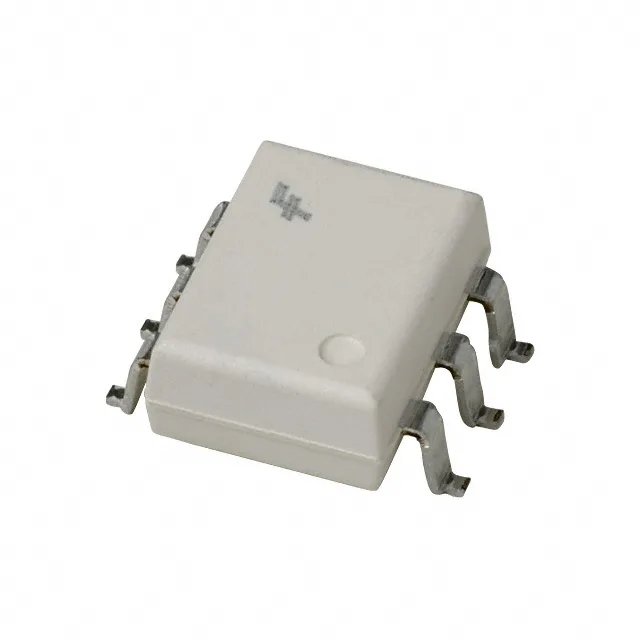
Isolation voltage and signal transfer in a 6-SMD gull wing
The H11A2SR2M provides 7500Vpk isolation between input and output — this is the peak repetitive voltage the optocoupler withstands across the isolation barrier, not a continuous rating. For a 60 Hz mains circuit, 7500Vpk corresponds to roughly 5300 VAC RMS, which covers reinforced insulation requirements in many industrial and medical power supplies. Minimum current transfer ratio is 20% at 10 mA forward current — meaning with 10 mA through the input LED, the output phototransistor can sink at least 2 mA. This floor sets the minimum load current the output can drive; below 20% CTR the output may not saturate reliably, so the downstream logic input must be sized for this minimum. Typical turn-on and turn-off times are 2 µs each — the optocoupler switches in the low-microsecond range, suitable for 100 kHz class signals but not for high-speed data links. The 2 µs propagation delay adds to the system timing budget; a 10 kHz PWM signal at 50% duty has a 50 µs half-cycle, so the 2 µs delay represents 4% timing error.
Package, mounting, and temperature grade
Surface-mount 6-SMD gull wing package — the leads extend laterally from the body, providing a visible solder fillet for inspection. The 6-SMD footprint is standard for this class of optocoupler; the gull wing form factor allows the part to sit flat on the board without a through-hole hole pattern. The 100°C upper limit means the part should not be placed near high-power dissipating components without thermal analysis. Maximum forward current is 60 mA DC — the input LED is rated for continuous drive up to this level. Above 60 mA the LED degrades and the CTR drops permanently. Typical forward voltage is 1.18 V at rated current, so the series resistor for a 5 V logic drive would be (5 - 1.18) / 0.01 = 382 ohms for 10 mA operation.
Sourcing is through independent distribution channels; quantities are confirmed at RFQ and are lot-specific. The base product number is H11A, a long-running optocoupler family with multiple CTR and package variants. Any substitution requires verifying the CTR bin, isolation voltage, and package footprint against the BOM.