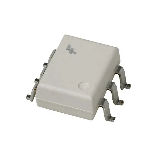
The 4N37SVM: Rated 4170Vrms isolation between input and output — this is the one-minute hipot test voltage, not the continuous working voltage. For a reinforced isolation barrier at mains voltage (250Vrms continuous), the 4170Vrms test provides margin above the 3750Vrms minimum typically required by IEC 60950-1 for basic isolation. The actual creepage and clearance depend on the PCB layout under the 6-SMD package. The 1.18V typical forward voltage at 10mA forward current means the LED side drops well within a standard 3.3V or 5V logic supply, leaving headroom for the series current-limiting resistor.
100% CTR at 10mA — sizing the load side
Minimum current transfer ratio of 100% at 10mA forward current means the output transistor can sink at least as much collector current as the LED draws. With a 30V output max and 300mV saturation voltage, this optoisolator drives a 5V logic input or a low-current relay coil directly — no external buffer needed for loads under 10mA. 2µs turn-on and 2µs turn-off time (typical) sets the switching ceiling at roughly 250kHz for a 50% duty cycle signal — well above the 10-100kHz range of most isolated gate-drive or feedback-loop applications. The symmetrical rise and fall times simplify timing margin calculations in the firmware.
Temperature range and package integration
Operates from -40°C to 100°C — the industrial temperature band covers outdoor telecom cabinets, motor-drive enclosures, and factory-floor PLC racks without derating. The 60mA absolute-maximum forward current gives headroom above the 10mA test point for driving the LED harder in low-CTR applications. Surface-mount 6-SMD gull wing package (6-SMD footprint) — the gull wing leads provide visual solder-joint inspection access and some compliance for CTE mismatch between the optoisolator and the PCB.