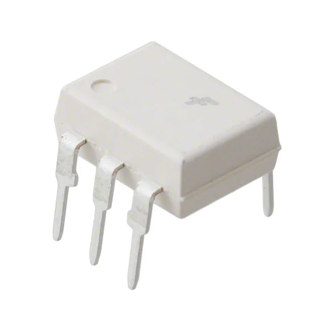
4170Vrms isolation in a 6-DIP through-hole package
The onsemi 4N26M_F132 is a single-channel optoisolator in the 4N26 family, providing 4170Vrms of galvanic isolation between a DC input LED and a phototransistor output with a base terminal accessible. The 6-DIP (0.300", 7.62mm) through-hole package sits in a standard DIP socket or solders directly into a plated-through-hole board — the 2.54mm pin pitch matches legacy and industrial PCB layouts where surface-mount reflow is not an option.
Transfer ratio and switching speed — what they mean for the receiver circuit
The minimum current transfer ratio is 20% at 10 mA forward current — meaning with 10 mA into the LED, the phototransistor can sink at least 2 mA at the output. This sets the pull-up resistor ceiling in the receiver: a 5V logic rail with a 2.2kΩ pull-up draws about 2.3 mA, which the output can just saturate at the 20% CTR floor. The 500 mV Vce saturation maximum at that collector current means the output drops under half a volt when fully on — enough margin for TTL or 3.3V CMOS logic thresholds. Turn-on and turn-off times are both 2 µs typical — a combined 4 µs propagation delay that limits the switching frequency to roughly 100 kHz before the output pulse width starts to shrink. For a 24V PLC input module sampling at 1 kHz, this is irrelevant; for a 50 kHz PWM isolation path, the 2 µs asymmetry between on and off edges introduces duty-cycle distortion that must be accounted for in the timing budget.
Industrial temperature range and output voltage ceiling
The maximum collector-emitter voltage is 30V, which limits the output side to 24V nominal supplies with 6V of headroom for transients; a 48V bus would exceed the rating.
onsemi has marked the 4N26M_F132 as Obsolete. The 4N26 family has been produced by multiple manufacturers over decades, so functionally equivalent parts from other brands exist in the same 6-DIP footprint, but no pin-compatible second-source is formally documented in the onsemi records.