Isolation barrier and signal transfer
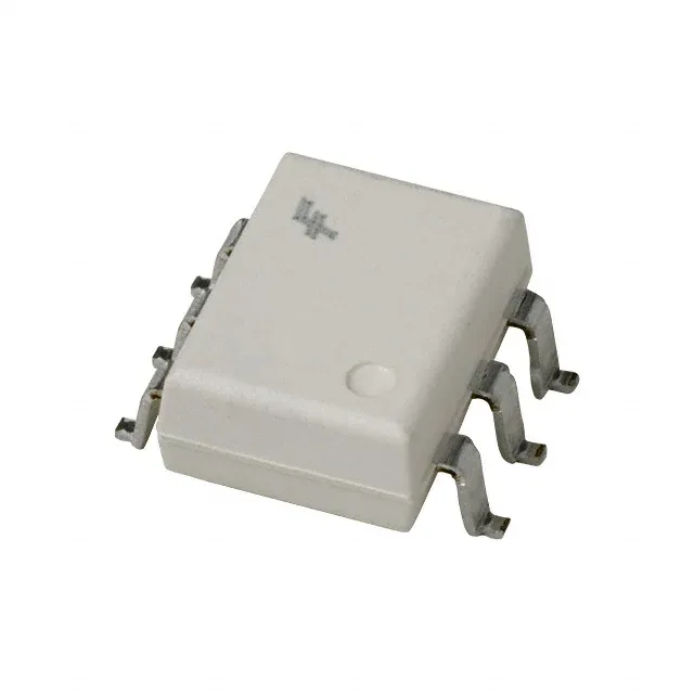
The 4N25SR2VM is a single-channel phototransistor optoisolator from onsemi, built around a GaAs infrared LED and a silicon NPN phototransistor in a 6-SMD Gull Wing package. Its 4170Vrms isolation voltage defines the safety barrier between the input and output circuits — enough for reinforced insulation in mains-powered equipment where the control side must stay galvanically separated from the high-voltage bus. The DC input type means the LED is driven by a steady forward current — no AC line rectification is needed. With a typical forward voltage of 1.18V and a maximum DC forward current of 60 mA, the input side is compatible with standard 3.3V or 5V logic outputs through a series resistor.
Current transfer ratio and switching speed
The minimum current transfer ratio (CTR) is 20% at 10 mA forward current — this is the coupling efficiency floor. For a given input current, the output phototransistor collector current will be at least one-fifth of the LED drive. That ratio sets the pull-up resistor value on the output side and determines whether the output swings rail-to-rail within the logic threshold. Turn-on and turn-off times are both 2 µs typical, giving a combined propagation delay of about 4 µs. This limits the usable signal bandwidth to roughly 100 kHz for digital signals — adequate for slow GPIO isolation, relay drivers, or status feedback, but not for high-speed data links. The output is a phototransistor with the base brought out to a separate pin. This lets the designer add a base-emitter resistor to speed up turn-off by bleeding stored charge, or bias the base for a specific operating point — useful when the CTR variation across temperature must be tightened.
Package, temperature range, and sourcing
The 6-SMD Gull Wing package has a standard 7.62 mm (300 mil) body width and a 1.27 mm pin pitch — the same footprint as the DIP-6 through-hole version, but in a surface-mount format that reflows on a standard lead-free profile. Operating temperature spans -40°C to 100°C, covering industrial control cabinets, power supply feedback loops, and motor drive interface boards. The maximum Vce saturation is 500 mV, and the output can handle up to 30V collector-to-emitter.