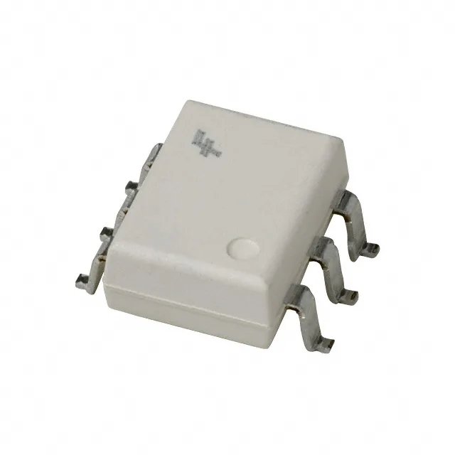
The onsemi 4N25FVM is listed as Obsolete by the manufacturer. Sourced through independent distribution channels against an RFQ.
Rated for 7500Vpk isolation — this is a reinforced-level isolation barrier for a phototransistor optocoupler in a 6-SMD Gull Wing package. Suitable for applications where the primary and secondary circuits must be galvanically separated, such as in power-supply feedback loops, motor-drive interface signals, or medical equipment where patient-contact isolation is required. Minimum current transfer ratio (CTR) of 20% at 10 mA forward current means the output transistor conducts at least 2 mA collector current when the LED is driven with 10 mA. This sets the minimum load current the optocoupler can sink at the output side, which governs the pull-up resistor value and the noise margin in the receiving logic input. Typical turn-on and turn-off times of 2 µs each define the maximum switching frequency for clean pulse transmission. At 2 µs per edge, the practical data rate ceiling is roughly 250 kbps before pulse-width distortion becomes significant — adequate for 50/60 Hz line-sync feedback, relay-drive signals, or slow digital status lines. Operating temperature range of -55°C to 100°C covers the full industrial and military temperature envelope. The lower limit suits cold-start conditions in outdoor telecom or avionics; the upper limit stays within the junction temperature rating of the phototransistor.
Supplied in a 6-SMD Gull Wing package (6-SMD), surface-mount. The Gull Wing leads provide a visible solder joint for inspection and rework, and the 1.27 mm (0.050-inch) pitch is compatible with standard SMT assembly processes. The package footprint matches the industry-standard 6-pin DIP SMD pattern used by the 4N25 family. DC input type — the internal LED is driven with a DC forward current up to 60 mA max. The typical forward voltage is 1.18 V at rated current, so a 5 V logic output can drive it through a series resistor without a level shifter. Output is a phototransistor with base access — the base pin allows external biasing or a speed-up capacitor to reduce turn-off time, though in most designs the base is left open or tied to emitter through a resistor for noise immunity.