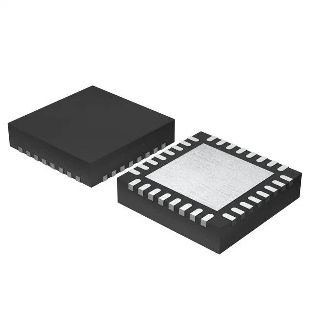
NXP USA Inc. LPC822M101JHI33K — Microcontrollers & Processors (MCU / MPU / DSP)

NXP LPC822M101JHI33K MCU — 32-bit ARM Cortex-M0+, 16KB Flash, 32-HVQFN

MPNLPC822M101JHI33K
Active

NXP LPC822M101JHI33K, ARM Cortex-M0+ 32-bit MCU, 30MHz, 16KB FLASH, 4KB SRAM, 29 I/O, I²C/SPI/UART, 12-bit SAR ADC ×12, 1.8–3.6V supply, −40 to 105°C, 32-HVQFN (5×5) exposed pad, Surface Mount, Tray, Active ROHS3.

$2.7000Ref. price · indicative, final on quote
Packaging32-VFQFN Exposed Pad
StockContact for availability
MOQ1 pcs
  • 100% new & originalTraceable channels only — no refurbs, no pulls, no remarked parts.
  • Date & lot codes on quoteStated per line before you commit; label photos on request.
  • MSL-compliant ESD packingMoisture-sealed bags with indicator cards; reels photo-verified.
  • PayPal buyer protectionPay by T/T, PayPal or Payoneer — card payments covered end to end.

Specifications

LPC822M101JHI33K Technical Specifications
ParameterValue
SeriesLPC82x
Mounting typeSurface Mount
Oscillator typeInternal
Program memory typeFLASH
Voltage - supply (Vcc (Vdd))1.8V ~ 3.6V
Operating temperature-40°C~105°C(TA)
Speed30MHz
PackageTray
RAM size4K x 8
Core size32-Bit Single-Core
PeripheralsBrown-out Detect/Reset, DMA, POR, PWM, WDT
ConnectivityI²C, SPI, UART/USART
Number of i (O)29
Core processorARM® Cortex®-M0+
Case32-VFQFN Exposed Pad
Data convertersA/D 12x12b SAR
Program memory size16KB (16K x 8)

Frequently asked questions

What does the 105°C operating temperature mean for a sealed IP67 enclosure?

The 105°C rating is the absolute maximum ambient under the JESD51-3 thermal test board conditions. In a sealed enclosure the internal ambient will exceed the external ambient; the junction temperature depends on the thermal resistance from the exposed pad through the PCB vias to the enclosure airspace. Model the pad thermal path before specifying the enclosure — the 105°C Ta is not a licence to run the part at the package limit in a sealed box without derating.

What I/O count is left for a fieldbus codec after the peripherals are mapped?

29 I/O is the gross count. A SPI codec consumes at minimum two pins (MOSI/MISO) plus a chip-select; a UART codec consumes two pins; an I²C host consumes two. With the ADC taking 12 channels and the debug interface occupying a small subset, the free GPIO count for discrete signalling or additional fieldbus daisy-chaining narrows significantly — the I/O map must be pinned out before the PCB layout is fixed.