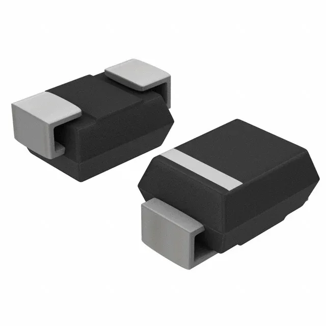
90V rail clamp — 1500W peak pulse in DO-214AB
The 90V reverse standoff voltage means the diode remains non-conducting below that rail voltage, drawing negligible leakage current during normal operation. The 100V minimum breakdown voltage is the threshold where avalanche conduction begins — a 10V guard band above the standoff ensures the part does not clip normal line ripple.
Clamping voltage and surge current — the BOM-fit numbers
At the 9.4A peak pulse current, the clamping voltage is 160V maximum. That 160V ceiling must stay below the absolute-maximum rating of any downstream semiconductor on the same rail — a 200V MOSFET or 180V-rated capacitor leaves only 20V of margin, which is tight for repetitive surges. The 1500W peak pulse power is derated linearly above 25°C; at 125°C ambient the effective power drops to roughly 60% of the rated value — account for that in the thermal budget if the board runs hot.
For a 90V rail application, the clamping voltage of 160V and the 1500W pulse rating are the primary selection axes. If the downstream components are rated for 180V or higher, the margin is comfortable; if they are 150V-rated, the SMCJ90E3/TR13 may not provide enough headroom and a higher-voltage TVS (e.g., SMCJ100A) should be evaluated.