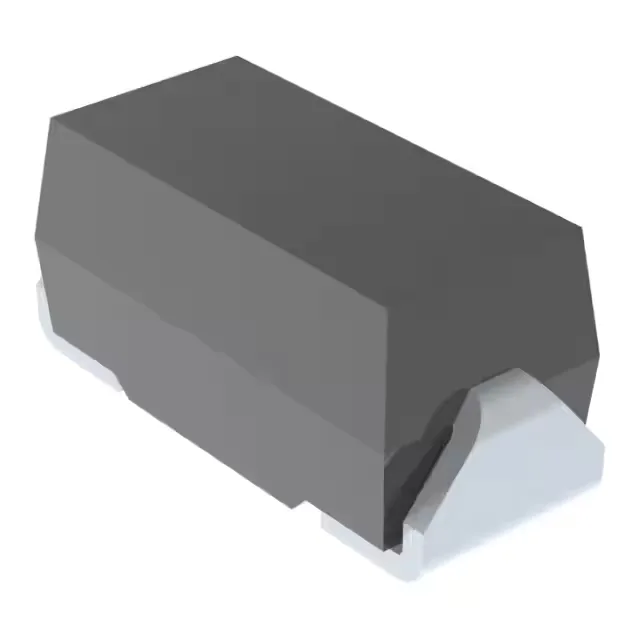
What this TVS diode does on your board
It clamps transients at 12V maximum, protecting downstream circuitry on a 7V nominal rail. The 7V reverse standoff voltage means it starts conducting above the normal operating level, so a 5V or 3.3V supply line would see the clamp trigger well above the rail — this part is sized for a 7V bus, not lower.
Peak pulse current and clamping — the so-what for your BOM
With a peak pulse current of 41.7A (10/1000µs) and a breakdown voltage minimum of 7.78V, the diode absorbs surge energy without letting the protected line exceed 12V. The 500W rating is the product of clamp voltage and peak current — a standard metric for comparing TVS devices in the same package class. The DO-214AC (SMA) package is a common footprint, so reflow profiles and pad layouts are well documented.
Microchip lists the SMAJ7.0AE3/TR13 as Active. No single-source exposure — the SMAJ7.0 base number is widely distributed.
Design-in checklist for the DO-214AC package
The DO-214AC (SMA) footprint uses standard land patterns per IPC-SM-782. The cathode band on the body identifies the unidirectional orientation — reverse insertion bypasses the protection. No power line protection feature — this is a signal-line or low-power rail TVS, not a mains-side suppressor. For 5V protection, a lower standoff voltage part (e.g., SMAJ5.0A) would be the correct choice.