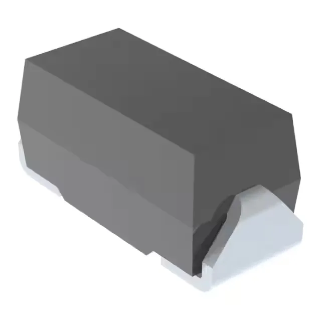
5V rail protection in a DO-214AC package
Its 5V reverse standoff voltage means it sits across the supply without conducting until a surge pushes it into breakdown at 6.4V minimum. The 9.2V maximum clamping voltage at 54.3A peak pulse current tells you the worst-case voltage the protected load sees during a 10/1000µs surge event — useful for checking the downstream device's absolute maximum rating. Rated for 500W peak pulse power, this part handles moderate-energy transients common in general-purpose applications like power-supply input protection, relay coil suppression, or I/O line clamping.
Clamping voltage and surge current — the protection window
The 6.4V breakdown minimum ensures the diode does not leak at 5V nominal. The 9.2V clamp at 54.3A is the ceiling — any spike above that is shunted. For a 5V CMOS rail with a 6V absolute max, this part leaves 3.2V of headroom; for a 3.3V rail it would clamp too high, so match the standoff voltage to your rail. If your application uses a different pulse shape (8/20µs for ESD, 10/700µs for telecom), the peak current capability shifts; derate per the datasheet's pulse-duration curve.
For a BOM line, this part is safe to design in without a near-term replacement risk. The DO-214AC package is MSL 1 typically, so no special bake-out before reflow.