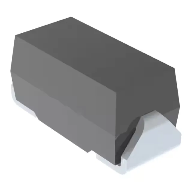
130V rail protection in a DO-214AC footprint
Its reverse standoff voltage of 130V (typ) means it sits across the supply without conducting until a surge pushes past the 144V minimum breakdown threshold. At that point it clamps at 209V maximum while shunting 2.4A peak pulse current (10/1000µs waveform) — enough to absorb a 500W pulse without letting the downstream silicon see overvoltage.
Breakdown, clamp, and current — the transient budget
The 144V minimum breakdown voltage gives a guard band below the 209V clamp ceiling. For a 130V rail that normally sees 140V during brownout or startup, the TVS stays off. The 2.4A peak pulse current at the 10/1000µs waveform is the current the diode must survive — the 500W peak pulse power is the product of clamp voltage and current. If your transient source impedance is low, the diode will clamp harder; the 209V ceiling is the worst-case voltage the protected circuit sees.
Microchip lists the SMAJ130AE3/TR13 as Active.
Rework and footprint — DO-214AC under the hot air
The DO-214AC (SMA) body is a two-terminal SOD-123-like outline with a cathode band on the top. It reflows well with a standard lead-free profile; the small thermal mass means it doesn't soak heat into the board. Orientation is unambiguous: the cathode band faces the positive rail side.