What this 8-bit PIC brings to a CAN-node design
The Microchip PIC18F2580-I/ML is an 8-bit MCU from the PIC® 18F family, built around a 40 MHz core that delivers up to 10 MIPS.
At 40 MHz, each instruction cycle takes 100 ns (four clock cycles per instruction in the PIC18 architecture). That is enough headroom to run a CAN message-handler interrupt, update a PWM output, and poll an ADC channel within a 1 ms control loop. The 8-bit data path means 32-bit arithmetic takes multiple cycles, so this is not a DSP replacement — but for real-time CAN messaging and logic control, the timing margin is comfortable.
CAN on board — no external controller needed
The PIC18F2580 embeds a CAN 2.0A/B protocol engine that handles message framing, arbitration, and error detection in hardware. You still need an external CAN transceiver (like an MCP2551) to convert the digital CAN-TX/CAN-RX signals to the differential bus levels, but the MCU itself does the heavy lifting. That integration saves board space and BOM cost versus a separate CAN controller IC. The peripheral set also includes a 10-bit ADC with 8 channels, two PWM generators, and a watchdog timer — enough to build a self-contained CAN node without extra glue logic.
28-QFN with exposed pad — thermal and assembly notes
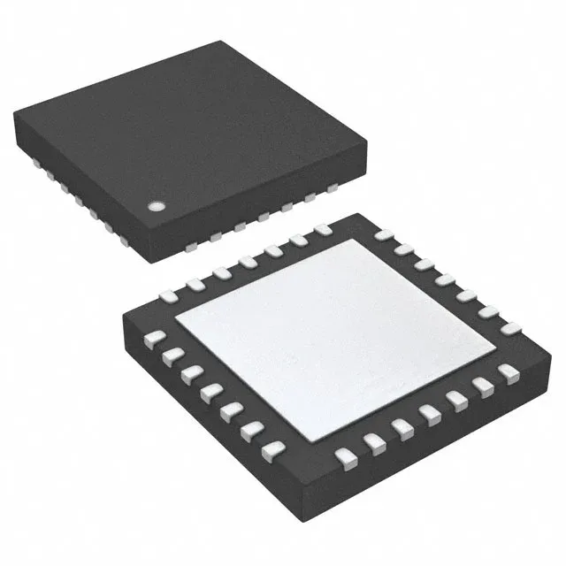
Housed in a 28-VQFN (6x6 mm) with an exposed pad, this part is meant for reflow soldering. The small footprint helps in space-constrained designs, but the QFN package requires a solder-paste stencil and X-ray inspection for voiding; hand-soldering is impractical.
Supply range and operating conditions
Brown-out detect and power-on reset are built in, so external supervisor ICs are optional for all but the most stringent safety designs.
Microchip lists the PIC18F2580-I/ML as Active. That means no end-of-life notice is pending, and the part is still supported for new designs. It is a current-production catalog item, not a last-time-buy or NRND part.