8-bit PIC at 4 MHz — what the clock buys you
The 4 MHz ceiling sets the instruction throughput at 1 MIPS (one instruction per clock cycle for most instructions, per the PIC16 architecture). For a firmware engineer, this means timing loops and peripheral baud rates are budgeted against a deterministic 1 µs instruction cycle — no flash wait-state surprises at this speed.
Low-voltage operation — the LF advantage
The 'LF' in the order code signals the low-voltage variant: the supply range extends from 2 V to 5.5 V, compared to the standard PIC16F874 which requires a minimum of 4.0 V. The full 4 MHz operation is guaranteed down to 2 V, so the clock speed does not derate with the supply.
On-chip resources and peripheral set
128 x 8 bytes of EEPROM provide non-volatile storage for calibration constants or configuration parameters without wearing the Flash. The peripheral set includes a 10-bit ADC with 8 channels, two PWM outputs, a Brown-out Reset and Power-on Reset, and a Watchdog Timer.
44-TQFP footprint and layout notes
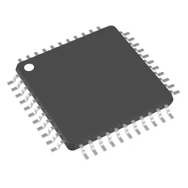
The 44-TQFP package measures 10x10 mm with a 0.8 mm pitch — a common footprint that routes cleanly on two-layer boards if the I/O count is kept under 25. Decoupling with a 100 nF ceramic per supply pair is standard; the wide 2 V to 5.5 V range means the regulator output tolerance is less critical than on a 1.8 V-only part.
The part is ROHS3 compliant.