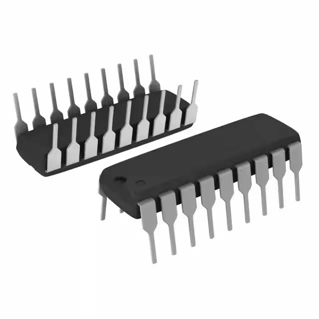
OTP memory locks the firmware — no field updates possible
The Microchip PIC16HV540-04I/P is an 8-bit PIC MCU with 768 bytes of one-time programmable (OTP) program memory, 25 x 8 bytes of RAM, and a 4 MHz external-oscillator core. The OTP means the firmware is permanent once programmed — there is no erase cycle, no field update, no bug fix after the production run. This part is for designs where the code is frozen and the BOM must never see a reprogramming step.
The supply range spans 3.5 V to 15 V, which covers 5 V and 12 V nominal rails without a preregulator. In a motor-drive control board or an industrial sensor head where the bus voltage swings, this MCU can ride through the ripple as long as the brown-out detect (BOD) is enabled. The 12 I/O lines are 5 V-tolerant at the high end of the supply, but the I/O voltage follows Vdd — if the system needs 3.3 V logic interface, the supply must be set to 3.5 V minimum.
4 MHz core — what the timing means
At 4 MHz the instruction cycle is 1 µs (four clock cycles per instruction for the PIC architecture). That sets the polling-loop ceiling and the timer resolution. For a 50 Hz PWM update or a 1 kHz sensor read, the headroom is ample. For bit-banged serial protocols above 100 kbaud, the timing margin gets tight — the UART-less design must account for the 1 µs instruction granularity.
Package and mounting — through-hole for hand-assembly or rework
Housed in an 18-pin PDIP (0.300-inch row spacing), the PIC16HV540-04I/P is a through-hole part. No reflow profile needed — it plugs into a socket or wave-solders into a plated-through-hole board. The 18-DIP footprint is standard and matches legacy PIC16C5x sockets. For a prototype run or a low-volume industrial controller, this package is easier to handle than a surface-mount QFN.
The 85°C ceiling covers most sealed enclosures without active cooling. The brown-out reset and watchdog timer (WDT) provide basic fault recovery in noisy environments.
For dual-sourcing or a drop-in replacement, the PIC16LF1559-I/SS shares the same PIC core and 8-bit architecture but uses Flash memory and surface-mount packaging; it is not a pin-compatible substitute but a functional alternative for new designs that need reprogrammability.