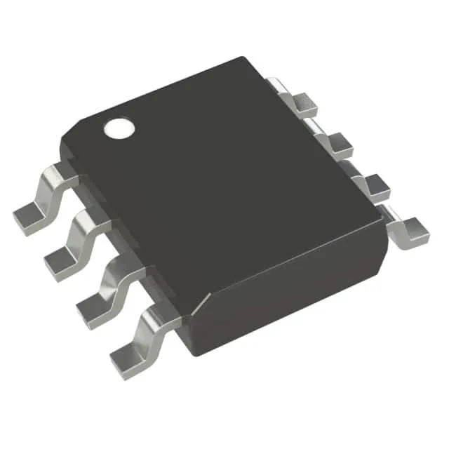
What this 8-pin PIC brings to a control board
The Microchip PIC12F1840T-I/SN is an 8-bit PIC MCU from the PIC® XLP™ 12F series, built around a 32 MHz core with 7 KB of Flash program memory, 256 bytes of RAM, and 256 bytes of EEPROM. On-chip peripherals such as brown-out reset, power-on reset, PWM, and watchdog timer reduce external component count for simple control loops and supervisory functions.
The 32 MHz clock rate is the top end for this 8-bit PIC family. At this speed, single-cycle instruction execution reaches about 8 MIPS, enough for real-time control loops such as sensor polling at a few kHz, PWM generation up to tens of kHz, and serial communication at standard baud rates (e.g., 115200 bps UART, 1 MHz I²C). The 7 KB Flash and 256-byte RAM limit firmware complexity — think state machines, PID loops, or simple protocol handlers rather than a full TCP/IP stack. If clock accuracy better than ±2% is needed, the design can switch to an external clock source.
With 7 KB of Flash (4K x 14 words) and 256 bytes each of RAM and EEPROM, the memory budget is tight. The 256-byte EEPROM is useful for storing calibration constants, configuration parameters, or fault logs that must survive power loss — no external serial EEPROM needed. The 256-byte RAM limits variable storage, so firmware must be written with register usage in mind, often relying on the hardware stack and file registers.
At the low end, the device can run from two alkaline cells (2.4 V fresh, 2.0 V depleted — note the 2.3 V minimum means a boost converter or third cell may be needed near end-of-life). The XLP (Extreme Low Power) technology typically draws microamps in sleep mode, making it suitable for battery-powered sensors that wake briefly to take a reading and transmit.
This removes the sourcing risk of an imminent last-time-buy for new designs. For dual-sourcing or a pin-compatible alternative, the PIC16LF1559-I/SS is a related 8-bit PIC in a 20-pin SSOP package — note the different pin count and package, so a board redesign is required.