PIN diode parametrics for RF switching and attenuation
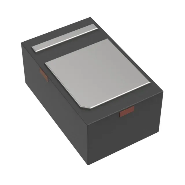
The MMP4402-GM2 is a single PIN diode from Microchip Technology's MMP4400 series, housed in an 0805 (2012 Metric) surface-mount package. It is designed for RF switching, attenuator, and limiter circuits where low capacitance and low series resistance are critical to maintaining signal integrity through the band. With a peak reverse voltage rating of 500 V, this diode can handle high-voltage RF environments such as transmit/receive switch networks in base stations or radar front-ends. The 0.5 pF capacitance at 50 V reverse bias and 1 MHz sets the off-state isolation — lower capacitance means better isolation at higher frequencies, which is the primary selection axis for a PIN diode in a shunt switch topology. Forward resistance is 650 mOhm at 100 mA forward current and 100 MHz. This figure determines the insertion loss when the diode is forward-biased (on state); a lower resistance reduces the signal loss through the switch. For a typical 50-ohm system, 650 mOhm contributes roughly 0.11 dB of additional loss — well within the budget for most RF chains.
Thermal and package constraints for board integration
The 0805 package footprint is the primary layout constraint — the copper pad area under the terminations sets the thermal resistance to the board. Maximum power dissipation is 4 W, but this is the absolute limit at 25 °C case temperature; in practice, the continuous RF power the diode can handle is derated by the board's ability to sink heat. For a 50-ohm system at 1 GHz, the thermal limit typically becomes relevant above +30 dBm continuous wave input power. The 150 °C upper limit is the junction temperature — the board temperature at the solder joint must stay lower to keep the junction within rating.
Active lifecycle and compliance status
The 0805 package is a standard EIA footprint, so no special nozzle or feeder setup is required beyond the usual 0805 profile.