Noise-sensitive rail — the PSRR is the spec that matters
The MIC5365-2.0YMT-TZ is a fixed 2V output LDO rated for 150 mA continuous, with a PSRR of 80 dB at 1 kHz rolling off to 65 dB at 10 kHz. That means it knocks down switching-regulator ripple by a factor of 10,000 at 1 kHz — enough to keep a 1 mVpp ripple from a buck converter down to 0.1 µV at the LDO output. For analog front-ends, ADC reference rails, or RF bias supplies, this is the difference between a clean signal and one that carries the converter's switching artifact. The 150 mA current ceiling fits low-power sensor nodes, wireless modules, and always-on microcontrollers that draw tens of milliamps. The 39 µA quiescent current means the regulator's own consumption doesn't dominate the sleep-mode budget — a coin-cell-powered device that spends most of its time in deep sleep still gets years of shelf life.
Dropout and thermal — the real-world margins
Maximum dropout is 0.38 V at the full 150 mA load. If the input rail is 2.5 V, the headroom is only 0.12 V above the 2 V output plus dropout — that's tight. A 3.3 V rail gives 0.92 V of margin, plenty for the regulator to stay in regulation across temperature and load transients.
Package and board-fit realities
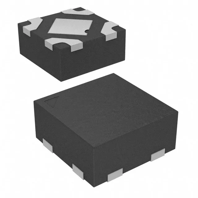
The 4-UDFN exposed pad (also called 4-TMLF®) is a 1x1 mm body with four peripheral lands and a central thermal pad. The 0.5 mm pitch means the lands are small — a standard 0.3 mm drill for the via-in-pad under the thermal pad is acceptable, but the via must be filled or tented to prevent solder wicking. The exposed pad is the main heat path; a 2x2 via array with 0.2 mm finished hole size under the pad gives a junction-to-board thermal resistance around 50°C/W. The enable pin (active high) lets the system power down the LDO when the load is idle, cutting the quiescent current to near zero. Tie it to the input if always-on operation is needed — but leave it unbounded at your own risk; a floating enable can couple noise into the bandgap reference.
Lifecycle and sourcing posture
The 4-TMLF® package is moisture-sensitive — verify the MSL level on the reel label before exposing to reflow without bake.