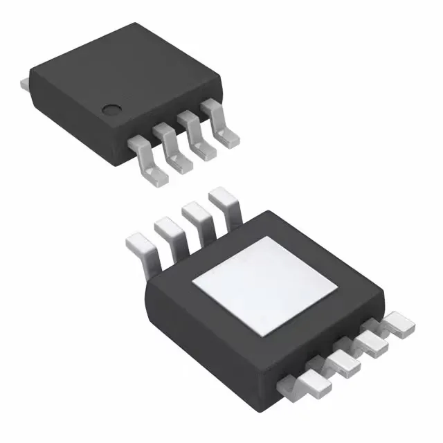
1.8V and 2.8V fixed rails — the dual-output LDO for mixed-voltage domains
The MIC5357-MGYMME is a dual-output low-dropout linear regulator from Microchip Technology, delivering fixed 1.8V on one channel and 2.8V on the other, each rated for 500 mA continuous output current. This makes it a direct fit for powering a 1.8V core or I/O domain alongside a 2.8V analog or memory rail from a single upstream supply up to 5.5V. The 300 mV maximum dropout at full load per channel means the input rail needs at least 2.1V for the 1.8V output and 3.1V for the 2.8V output to stay in regulation across the full current range. Below that headroom the output follows the input minus the dropout floor.
PSRR profile — where the 70dB at 1kHz matters
The power-supply rejection ratio is specified at 70 dB at 1 kHz, rolling off to 45 dB at 20 kHz. For a 1.8V rail feeding a PLL or ADC reference, that 70 dB at switching-regulator fundamental frequencies (typically 300 kHz to 2 MHz) is already degraded — expect roughly 30-35 dB in that band based on the 20 dB/decade roll-off typical of LDOs. If the upstream switcher runs at 1 MHz, the ripple attenuation is about 35 dB, meaning 10 mV p-p ripple at the switcher output becomes roughly 180 µV p-p on the LDO output. For a 16-bit ADC with a 2.8V reference, that is about 1.5 LSBs of noise — acceptable for most industrial acquisition but marginal for precision metrology. The 175 µA quiescent current (240 µA max supply current) keeps the LDO viable for always-on rails in battery-powered equipment — the regulator's own draw is comparable to a single LED indicator. Enable control lets the downstream rail be gated off entirely when the load is in sleep.
Thermal and protection — the exposed-pad reality
The 8-MSOP-EP package with exposed pad requires a thermal land on the PCB — the junction-to-ambient thermal resistance depends on the copper area soldered to the pad. At 500 mA per channel and 300 mV dropout, each channel dissipates 150 mW; total package dissipation of 300 mW in a 25°C ambient raises the junction about 50°C above ambient with a reasonable 2 cm² copper pour. At 125°C ambient the margin to the 125°C operating limit is zero — derate output current or reduce dropout voltage by raising the input rail. Over-current and over-temperature protection are built in — the LDO folds back or shuts down under fault. There is no reverse-current protection: if the output is held above the input when the LDO is disabled, current flows backward through the internal pass element. A Schottky diode from output to input is cheap insurance if the load can back-drive the rail.
Active lifecycle — no end-of-life pressure on the BOM
For a procurement desk managing a multi-year production run, this part does not carry the obsolescence risk that drives emergency redesigns. The ROHS3 compliance (no exemptions) means it ships without the lead-free deadline clock that ROHS2 exemptions carried.