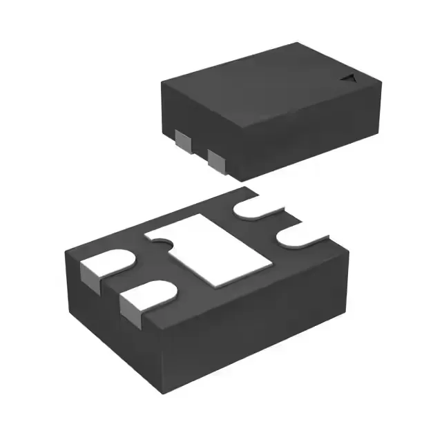
Package and board integration — 4-TMLF footprint
The MIC5303-3.3YMT-TR comes in a 4-VFDFN exposed pad package, also designated 4-TMLF® (1.2x1.6 mm). The exposed pad under the package is the primary thermal path — the PCB land pattern should mirror the pad dimensions and connect to a copper pour for heat spreading. The 0.5 mm pitch on the four peripheral leads is fine enough that a solder-mask-defined pad is recommended to prevent bridging during reflow.
PSRR across the audio band — what 65 dB to 42 dB means
Power supply rejection ratio (PSRR) is specified at 65 dB at 1 kHz, dropping to 42 dB at 20 kHz. This means that at 1 kHz, ripple on the input is attenuated by a factor of ~1,800; at 20 kHz, the attenuation factor drops to ~125. For an audio codec or ADC supply rail, the 20 kHz PSRR figure is the one that governs — switching regulator ripple at that frequency will pass through with less rejection than the 1 kHz spec suggests. The 120 µA quiescent current is the price paid for this rejection level; a lower-Iq LDO would typically show worse PSRR above 10 kHz.
Dropout and load regulation headroom
Maximum dropout voltage is 0.2 V at the full 300 mA output. With a maximum input of 5.5 V and a fixed 3.3 V output, the headroom between the input rail and the output must stay above 0.2 V across the full load range. A 3.6 V input rail at 300 mA leaves only 0.1 V margin — the regulator will drop out of regulation if the input sags below 3.5 V. The 120 µA quiescent current is drawn from the input regardless of load; in battery-powered designs this is the floor current that sets the standby runtime.
Protection and temperature range
Over-current and over-temperature protection are built in — the regulator folds back output current during a fault and shuts down if the junction exceeds the thermal limit. The enable pin allows the output to be gated; when pulled low, the regulator enters a shutdown state that drops the quiescent current below the 120 µA active figure.