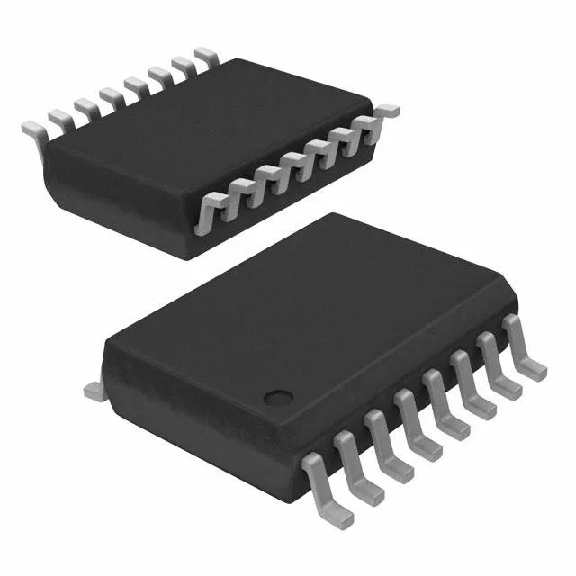
16-SOIC footprint and what it asks of the board
The MIC4468YWM-TR: Surface-mount assembly with Tape & Reel supply means it feeds straight into a pick-and-place line without a tube-handling step. Four independent low-side drivers in one package concentrate the gate-drive routing under the IC, which keeps the high-current loops tight — a layout advantage when driving paralleled MOSFETs from a single controller.
Four 1.2 A channels — what the peak current buys you
Each of the four channels delivers 1.2 A peak source and 1.2 A peak sink. That is enough current to charge and discharge the gate capacitance of a medium-power MOSFET (say, 10-15 nC Qg) in under 20 ns, which keeps switching losses low in a 200-500 kHz converter. The symmetric source/sink ratio means the turn-on and turn-off edges are balanced — no need to add a separate gate resistor for the turn-off path. Rise time is 14 ns typ and fall time 13 ns typ into a standard test load. Keep the driver-to-gate trace under 10 mm and use a local bypass cap between VDD and GND right at the IC pins.
Supply range and logic compatibility
The 4.5 V to 18 V supply range covers the common gate-drive rails: 5 V for logic-level MOSFETs, 12 V for standard power MOSFETs, and 15 V for IGBTs at the low end of their gate voltage. The logic input thresholds are 0.8 V (VIL) and 2.4 V (VIH), so a 3.3 V microcontroller output drives it directly — no level shifter needed between the PWM pin and the driver input. Non-inverting inputs mean the output follows the input polarity — no inversion to account for in the control loop.
Active lifecycle and compliance status
Microchip lists the MIC4468YWM-TR as Active, so there is no last-time-buy clock running and no risk of an abrupt EOL notice on the next PCN cycle. ROHS3 compliant — no exemptions expiring, which simplifies the declaration for EU-market equipment.