Fixed 1.8 V at 150 mA — the quiescent current is the headline
The Microchip MCP1711T-18I/OT is a single-output positive LDO that delivers a fixed 1.8 V rail at up to 150 mA from a maximum 6 V input. Its defining parameter for battery and always-on applications is a quiescent current of 1.27 µA — low enough that the regulator's own draw is often below the self-discharge rate of the battery it runs from. The enable pin lets the system cut that draw to near zero in sleep mode. Dropout is specified at 1.4 V maximum at the full 150 mA load, so the input rail needs to stay above 3.2 V to hold regulation; at lighter loads the dropout is lower, but the 1.4 V max is the figure to budget for worst-case headroom.
Dropout at 150 mA — headroom budget for the rail
A 1.4 V maximum dropout at 150 mA means this is not a low-dropout regulator in the modern sense — it needs roughly 0.8 V more headroom than a typical 200 mV-dropout LDO. That matters when the input is a 3.3 V rail that sags under load: a 3.3 V input dropping to 3.0 V still holds the 1.8 V output, but a 2.8 V rail would lose regulation. For designs running from a single Li-ion cell (nominal 3.7 V, end-of-discharge around 3.0 V), the margin is tight; a boost pre-regulator or a higher-voltage battery stack is safer. The trade-off for the ultra-low quiescent current is higher dropout — the part is optimised for standby efficiency, not tight input-output differential.
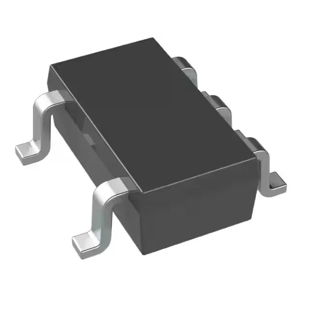
Housed in an SOT-23-5 (SC-74A, SOT-753) surface-mount package, the part occupies minimal board area — useful for space-constrained sensor nodes and wearables. The enable pin (active-high, standard logic levels) allows the system to power down the regulator and eliminate quiescent draw entirely in sleep states.