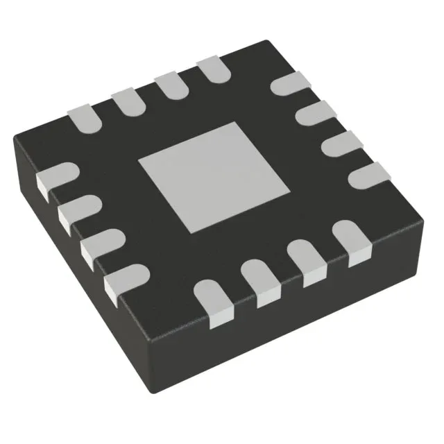
Topology flexibility in a 3x3 mm QFN
The MCP1633-E/MG: That means one BOM line covers isolated and non-isolated DC-DC stages in the same power range — useful when a design needs to hedge between a flyback for a bias supply and a SEPIC for a battery-powered rail that must regulate above and below the input. It switches from 200 kHz up to 2.2 MHz and supports clock synchronization, so you can park the switching noise outside a sensitive band or lock multiple converters to a common clock. The 90% max duty cycle sets the practical boost ratio — at 3 V in, the output can reach about 27 V before the duty ceiling forces a tapped-inductor or cascaded stage.
Package and thermal — the exposed pad is not optional
The package is surface-mount only — no socket, no hand-solder rework without a hot-air station. The tube ship format means the parts arrive in an antistatic tube, not tape-and-reel, so factor that into the pick-and-place feeder setup.
Control features for LED and general-purpose DC-DC
The controller integrates current limit, soft start, frequency control, and an enable pin — the soft start prevents inrush on a discharged output cap, and the enable lets a supervisor or GPIO gate the converter. The datasheet's title calls it a high-speed PWM controller with dimming, which points to LED drive as a primary application: the frequency control pin can accept a PWM dimming signal directly, modulating the LED current without an external DAC. Note the lack of synchronous rectification — the external Schottky diode handles the catch function, so the efficiency curve tops out around 90-92% depending on the diode's Vf and the switching frequency. At 2.2 MHz the diode recovery losses start to eat into the gain from the small magnetics; a 1 MHz design is usually the sweet spot for this part in a 12 V, 1 A SEPIC.