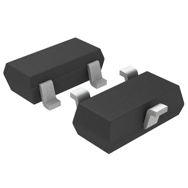
RF switch core — series PIN pair in SOT-23-3
The LXP1002-23-2 is a PIN diode configured as a 1 pair series connection, housed in a SOT-23-3 surface-mount package. This topology is the standard building block for RF switching and attenuator circuits where two series diodes share a common node. With a peak reverse voltage of 50 V and max forward current of 100 mA, the part handles moderate RF power levels typical of T/R switches in base stations or test equipment. The 4 Ohm series resistance at 100 mA and 100 MHz sets the insertion loss floor — lower resistance means less signal loss in the on-state. Capacitance of 0.32 pF at 50 V reverse bias and 1 MHz gives high off-state isolation at UHF frequencies. The low capacitance keeps the diode from coupling the RF signal when reverse-biased, which is critical for maintaining channel separation in multi-throw switches.
Temperature range and power dissipation
Rated for -55°C to +125°C operating junction temperature, the LXP1002-23-2 suits outdoor and industrial RF equipment that sees wide thermal swings. Maximum power dissipation of 250 mW limits the DC bias current under continuous operation — at 100 mA forward bias the voltage drop across the diode must stay below 2.5 V to stay within the dissipation budget. The SOT-23-3 footprint (TO-236-3 / SC-59 compatible) is a standard small-signal package with good thermal performance for this power level. Board layout should include a thermal via under the center pad if the diode is biased near the 250 mW limit in a high-temperature ambient.
RoHS3 compliant, with no exemptions that would restrict shipping to EU or other regulated markets. The part ships in a Bag — typical for small quantities of SOT-23 devices; reel packaging may be available by special request.