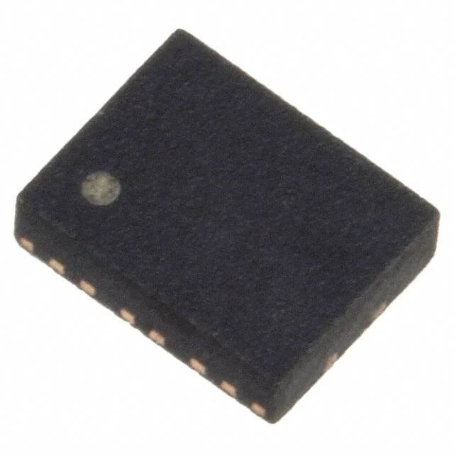
Microchip Technology DSC8121CL2-PROGRAMMABLE — Crystals & Oscillators

Microchip DSC8121CL2-PROGRAMMABLE MEMS XO, 10-170 MHz

MPNDSC8121CL2-PROGRAMMABLE
Obsolete

Microchip Technology DSC8121 series, XO (Standard) MEMS oscillator, DSC8121CL2-PROGRAMMABLE, CMOS output, 10 MHz ~ 170 MHz, ±25 ppm, -40°C ~ +105°C, 6-SMD No Lead.

Independent supplier — new & surplus stockAuthenticity-screened · ESD-safe packingListing updated Jul 2026

Specifications

DSC8121CL2-PROGRAMMABLE specifications
ParameterValue
TypeXO (Standard)
SeriesDSC8121
MountingSurface Mount
Supply voltage2.25V ~ 3.6V
Current - supply35mA
Current - supply (Disable)22 mA
Available frequency range10 MHz ~ 170 MHz
Frequency stability (Total)±25ppm
Operating temperature-40°C~105°C
Size (Dimension)0.126\" L x 0.098\" W (3.20mm x 2.50mm)
Height - seated0.035\" (0.90mm)
OutputCMOS
PackageTube
FunctionEnable/Disable
Base resonatorMEMS
Case6-SMD, No Lead

Product details

6-SMD package and board integration

The DSC8121CL2-PROGRAMMABLE: The no-lead construction keeps the parasitic inductance low for clean clock edges at 170 MHz. Max supply current is 35 mA at the highest frequency — a 170 MHz CMOS clock into a 15 pF load draws roughly that. The 22 mA disable current means the part still sinks power when gated off; a load switch on the Vdd rail would cut it to zero for ultra-low-power sleep states.

Sourcing reality — obsolete part

No official successor part number is recorded in the lifecycle data. This means the manufacturer no longer produces it, and any available units come from surplus or broker inventory.

Frequently asked questions

What is the closest pin-compatible alternative to the DSC8121CL2-PROGRAMMABLE?

There is no official successor recorded. Any alternative would need to match the 6-SMD No Lead 3.2x2.5 mm footprint, 2.25-3.6 V supply, CMOS output, and Enable/Disable function — and be factory-programmed to the same frequency. A quartz-based XO in the same package could work electrically but the pinout and enable logic must be verified against the board schematic.