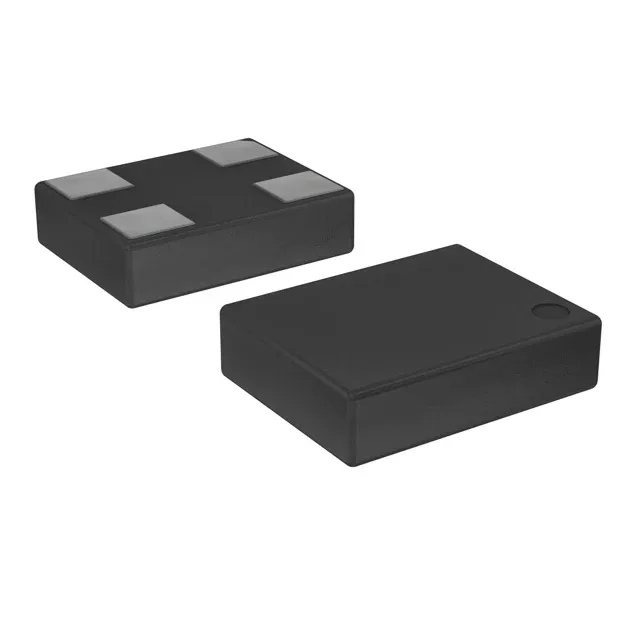
Obsolete — last-time-buy sourcing for existing BOMs
The DSC6101CI1A-024.0000T: The part carries AEC-Q100 automotive qualification, so it was originally selected into under-hood or chassis-domain clock trees. Replacing it in an existing BOM means finding a pin-compatible 24 MHz XO with the same 4-SMD no-lead footprint and ±50 ppm stability that also holds the AEC-Q100 rating.
24 MHz MEMS XO — CMOS output, wide supply range
A MEMS-based XO (Standard) generating a 24 MHz CMOS clock with an Enable/Disable pin — the output goes high-Z when the enable is pulled low, which lets the system clock gate without an external buffer. Typical current draw is 3 mA — low enough for always-on clocking in a battery-backed ECU. That is tight enough for a CAN or LIN node where the bit timing budget allows ±1 % tolerance; a quartz crystal with the same ppm spec would need external load capacitors, whereas the MEMS resonator integrates the tuning.
3.2 mm × 2.5 mm 4-SMD — board-fit note
The land pattern is the standard 4-pad oscillator footprint — no thermal pad, no exposed paddle — so a two-layer board with a solid ground pour under the part is sufficient. Surface-mount, supplied in Tape & Reel. The Enable/Disable pin is typically pin 1 on the 4-SMD package; verify the logic polarity against the downstream clock input before committing the BOM position.