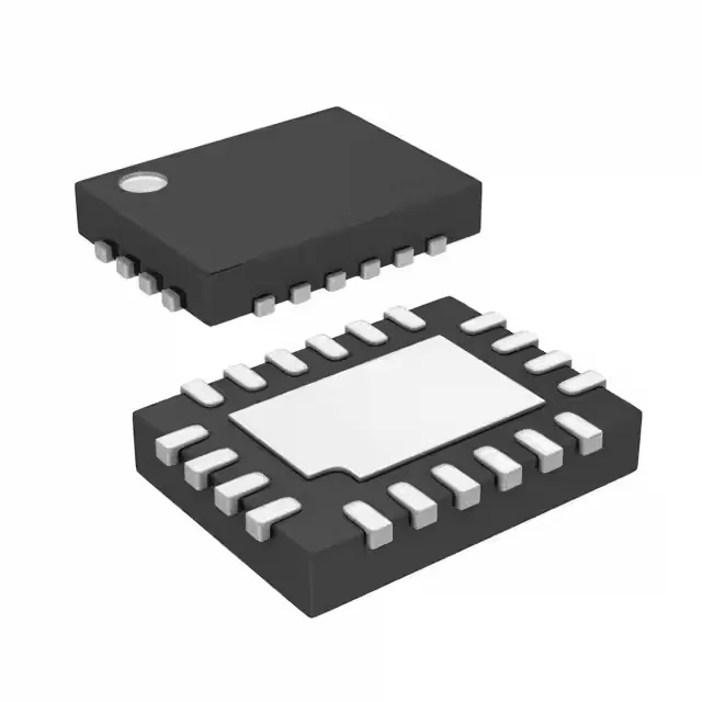
Microchip Technology DSC400-0444Q0009KE2 — Crystals & Oscillators

DSC400-0444Q0009KE2 MEMS XO – 100MHz HCSL, Active

MPNDSC400-0444Q0009KE2
Active

Microchip DSC400 series MEMS XO (Standard), 20-VFQFN exposed pad, 100MHz HCSL x3 outputs, ±25ppm stability, 2.25V~3.6V supply, -20°C~70°C operating range.

Sourced new & surplus through independent channelsAuthenticity-screened · ESD-safe packingListing updated Aug 2026

Specifications

DSC400-0444Q0009KE2 specifications
ParameterValue
TypeXO (Standard)
SeriesDSC400
Voltage2.25V ~ 3.6V
Frequency stability±25ppm
Frequency - output 1100MHz
Frequency - output 2100MHz
Frequency - output 3100MHz
Operating temperature-20°C~70°C
Height0.035\" (0.90mm)
Size (Dimension)0.197\" L x 0.126\" W (5.00mm x 3.20mm)
OutputHCSL
PackageTube
FunctionEnable/Disable
Base resonatorMEMS
Case20-VFQFN Exposed Pad

Product details

Active MEMS XO – three 100MHz HCSL lanes

Frequency stability is ±25ppm over the -20°C to +70°C commercial temperature range, which keeps the 100MHz HCSL edge placement within 250 ps of ideal across temperature — adequate for PCIe Gen1/2 reference clocks and high-speed serial links that budget 50-100 ppm total error. Supply voltage spans 2.25V to 3.6V, so the part runs directly off a 2.5V or 3.3V rail without an external LDO, and the enable/disable pin lets the system gate the outputs during low-power standby without cycling the main supply.

The 20-VFQFN exposed pad (5.00mm x 3.20mm body, 0.90mm height) requires a thermal via array under the paddle to conduct heat to the ground plane — without it, the junction temperature rises above the 70°C ambient ceiling during continuous HCSL switching. HCSL outputs are differential and require external 50-ohm termination to ground at the receiver per the HCSL standard — the oscillator itself does not include on-die termination, so the PCB layout must place the resistors within 0.5 inch of the load pins to maintain signal integrity at 100MHz.

Frequently asked questions

Does DSC400-0444Q0009KE2 have a built-in enable/disable feature?

Yes, the function is Enable/Disable. The enable pin gates all three HCSL outputs simultaneously — pulling it low puts the outputs into high-impedance state without removing the supply voltage, which saves power during system idle without a full power-cycle.