Four fixed-frequency outputs in one MEMS clock
Supply voltage spans 2.25 V to 3.6 V, covering both 2.5 V and 3.3 V logic rails without an intermediate regulator. The wide range also absorbs rail droop in battery-backed or lightly regulated systems — a single DSC400 can serve multiple board variants that run different core voltages. For a 12.288 MHz output, that is a maximum drift of ±614 Hz — tight enough for a USB audio clock or a CAN bus time base, but not for a GSM reference that demands sub-±10 ppm. If the application needs tighter stability, a TCXO or OCXO in the same footprint would be a different part number.
Package and layout: the exposed-pad thermal via pattern
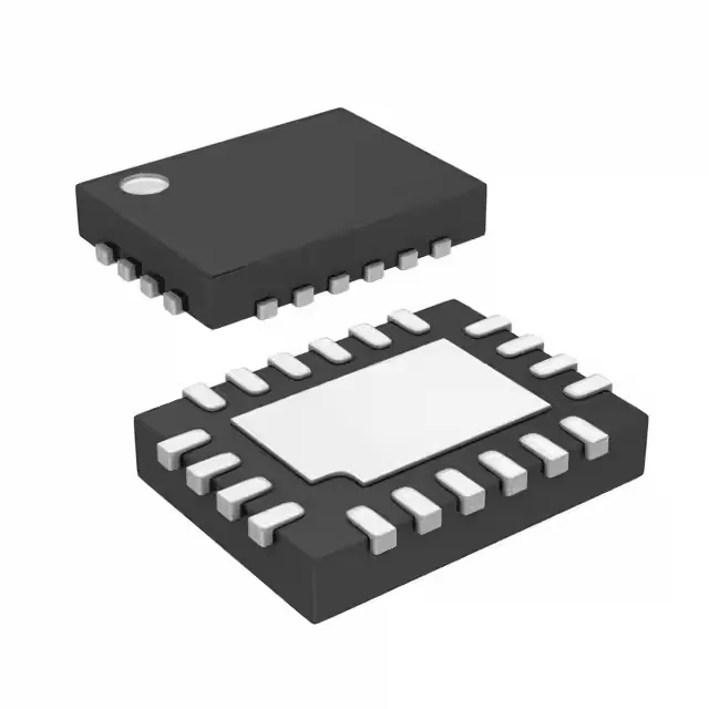
The 20-VFQFN exposed pad package (5.00 mm x 3.20 mm body, 0.90 mm height) requires a thermal via array under the centre pad to conduct heat to the PCB ground plane. The datasheet's recommended land pattern (not reproduced here) calls for a solder-paste stencil aperture that covers 50–70% of the pad area — a full-coverage stencil risks floating the package. The exposed pad is electrically connected to the die's ground reference, so the via pattern also serves as the low-impedance ground return for the output drivers. Tape & Reel (TR) packaging is standard for the DSC400 series. The 0.50 mm pitch of the VFQFN leads is fine for a two-layer board if the fan-out traces are necked to 0.15 mm under the package; a four-layer board with a dedicated ground plane under the pad is the safer choice for production repeatability.
The DSC400-0111Q0116KI1T is listed as Active. The base product number DSC400 covers a family of factory-programmed multi-output oscillators; if this exact frequency set is no longer needed in a future design, a different DSC400 variant with the same footprint and supply range can be ordered without a PCB spin. The DSC400 series does not have a pin-compatible second source from another manufacturer; cross-shopping should compare the full order code against the Microchip DSC400 configurator.