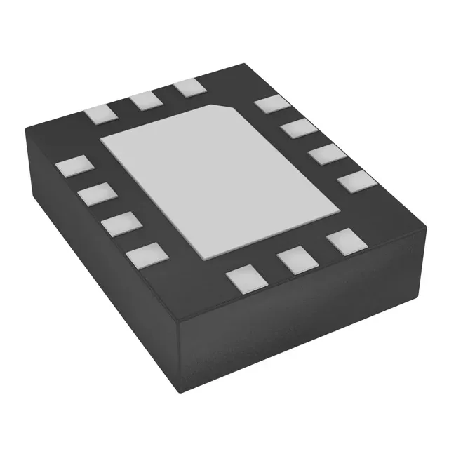
Microchip Technology DSC2033FI2-F0039T — Crystals & Oscillators

DSC2033FI2-F0039T MEMS XO 100 MHz / 75 MHz LVDS - Microchip

MPNDSC2033FI2-F0039T
Active

Microchip DSC2033FI2-F0039T, MEMS XO (Standard), dual LVDS outputs 100 MHz and 75 MHz, ±25 ppm stability, 2.25V–3.6V supply, -40°C to 85°C, 14-VFQFN exposed pad, tape and reel.

Independent supplier — new & surplus stockAuthenticity-screened · ESD-safe packingListing updated Aug 2026

Specifications

DSC2033FI2-F0039T specifications
ParameterValue
TypeXO (Standard)
SeriesDSC2033
Supply voltage2.25V ~ 3.6V
Current - supply38mA (Typ)
Current - supply (Disable)23 mA
Frequency stability±25ppm
Frequency - output 1100MHz
Frequency - output 275MHz
Operating temperature-40°C~85°C
Height0.035\" (0.90mm)
Size (Dimension)0.126\" L x 0.098\" W (3.20mm x 2.50mm)
OutputLVDS
PackageTape & Reel (TR)
FunctionEnable/Disable
Base resonatorMEMS
Case14-VFQFN Exposed Pad

Product details

Dual-frequency MEMS XO — 100 MHz and 75 MHz LVDS

The DSC2033FI2-F0039T is a MEMS-based XO (Standard) that delivers two independent LVDS clock outputs: 100 MHz on output 1 and 75 MHz on output 2, from a single 14-VFQFN exposed-pad package measuring 3.20 mm x 2.50 mm.

Active production — no LTB risk

It remains available for both new designs and production replenishment.

Enable/Disable function and supply current

The Enable/Disable pin lets the system gate the outputs: when disabled, supply current drops to 23 mA max from the 38 mA typ active draw — useful for power-sensitive designs that sequence clock domains.

Frequently asked questions

How can I order DSC2033FI2-F0039T or check availability?

Submit an RFQ for current pricing and lead time confirmation.

Is DSC2033FI2-F0039T a drop-in replacement for other 100 MHz LVDS oscillators?

This is a MEMS-based XO, not quartz. The 14-VFQFN exposed-pad package (3.20 mm x 2.50 mm) and dual-output LVDS scheme are specific to the DSC2033 series. Pin compatibility with other 100 MHz LVDS oscillators depends on the footprint and supply voltage — verify the pad layout and enable pin mapping against your existing BOM before substituting.