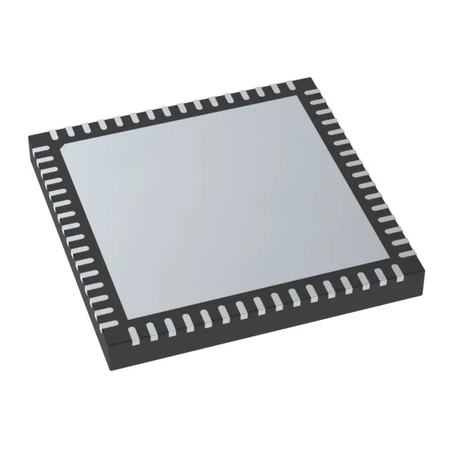
The ATSAMC21J18A-MUT: The part includes ECC on Flash, clock failure detection, and memory protection for safety-integrity designs.
48 MHz Cortex-M0+ — enough for real-time loops
The 48 MHz core provides single-cycle GPIO toggle rates and enough MIPS to run a field-oriented control motor loop with CANopen stack overhead.
CANbus connectivity — the main event
For a BOM decision: if your design requires CANopen or DeviceNet, this part saves you an external CAN controller chip and the associated SPI isolation overhead. The 52 available I/O give enough headroom to keep sensor inputs, PWM outputs for a 3-phase inverter, and a local human-machine interface on the same die without a port expander.
The series includes hardware diagnostic features for safety-functional designs, such as ECC on Flash, SRAM parity or ECC, and a built-in clock monitor.
Temperature grade and package — industrial deployment
The 64-VFQFN with exposed pad (9x9 mm) requires a good thermal via stitch under the pad if you are running the core at 48 MHz with all peripherals active above 70°C; the datasheet's thermal resistance figures assume a 2-layer board with the pad soldered to a copper plane.
Lifecycle and supply reality
There is no PCN or last-time-buy notice on this base part number as of the latest revision. No second-source alternate is officially cross-referenced by Microchip, but the SAM C21 family shares pin-compatible density options (128 KB and 256 KB Flash variants) if you need to adjust memory headroom without a PCB layout change.
Analog integration — ADC and DAC on-chip
The part carries 20 channels of 12-bit ADC and 3 channels of 16-bit ADC, plus a single 10-bit DAC. For a motor-drive BOM, the 16-bit ADC channels are typically reserved for current-sense feedback (shunt or Hall-effect), while the 12-bit channels handle voltage monitoring and temperature sensing. The DAC can generate an analog reference or a speed-setpoint voltage, reducing external op-amp count.