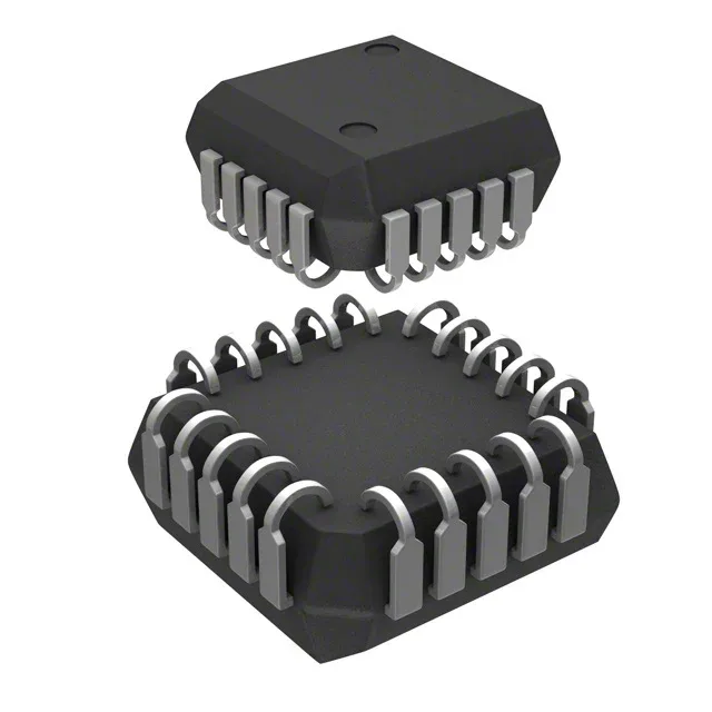
EE PLD with 8 macrocells — confirming the BOM match
The Microchip ATF16V8BQL-15JC is an electrically-erasable programmable logic device (EE PLD) from the 16V8 series, offering eight macrocells in a 20-lead PLCC package with J-leads for surface-mount assembly. It operates from a single 5V supply and is specified with a 15 ns propagation delay, which sets the timing budget for glue-logic replacement, address decoding, or state-machine integration in legacy 5V systems.
15 ns speed — what it buys on the bus
The 15 ns propagation delay means the PLD can handle combinatorial logic paths up to about 66 MHz in a typical 5V TTL environment, assuming reasonable fan-out and board parasitics. This is the figure that determines whether the part can meet setup-and-hold margins in a given address decode or chip-select path.
Microchip lists the ATF16V8BQL-15JC as Obsolete. Availability is through independent distribution and surplus inventory channels.
Package and footprint — PLCC-20 J-Lead
The 20-PLCC package (9x9 mm body) with J-leads is a surface-mount form factor distinct from the DIP or TQFP alternatives in the 16V8 family. The J-lead footprint requires a specific PLCC socket or a solder-paste stencil designed for the 1.27 mm pitch gull-wing profile.