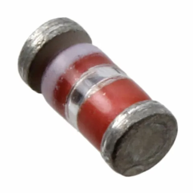
The 1N6677UR-1 is a 40 V Schottky rectifier rated for 200 mA continuous forward current in a DO-213AA surface-mount package. The 40 V reverse voltage ceiling suits it for clamping or rectifying on 12 V and 24 V rails where the peak transient stays under 30 V — the 10 V margin keeps the Schottky out of avalanche during inductive kickback. Forward drop is 500 mV maximum at 200 mA — the Schottky barrier delivers roughly half the Vf of a comparable PN-junction rectifier at this current, which directly reduces conduction loss in low-voltage supplies where every 100 mV of drop eats into the output headroom.
Reverse leakage and junction temperature — the thermal trade-off
Reverse leakage is specified at 5 µA maximum at 40 V. Schottky leakage doubles roughly every 10 °C above 25 °C junction — at 125 °C the leakage can approach several hundred microamps, which adds to the self-heating in a hot enclosure. The -65 to 125 °C junction range covers military temperature-grade environments, but the leakage at the hot end must be budgeted into the quiescent current of the powered circuit. Junction capacitance is 50 pF at 0 V bias, 1 MHz. In a 200 mA rectifier this capacitance is low enough that switching losses in a 100 kHz converter are negligible — the dominant loss term is the forward conduction drop, not the capacitive charge-discharge cycle.
DO-213AA surface-mount — footprint and board integration
The DO-213AA (also known as MELF-style) package is a cylindrical metal-electrode face-bonded component. The cathode band is marked on the body; the solder pads on the PCB must match the cylindrical contact area — a standard rectangular 0805 or 1206 footprint does not provide adequate solder fillet. The datasheet landing pattern calls for a concave pad profile that wraps around the barrel ends. Surface-mount assembly with DO-213AA requires careful pick-and-place nozzle selection — the cylindrical body can roll during placement if the vacuum pick-up is off-centre. Once reflowed, the joint reliability is comparable to a standard SMD package, but the visual inspection criterion differs because the solder fillet is at the barrel ends rather than under a flat lead.
This means it remains eligible for new designs and is supported through the standard Microchip distribution channel.