990 V blocking, 50 ns recovery — the switching rectifier for high-voltage rails
The Microchip Technology 1N6630 is a standard fast recovery rectifier rated for 990 V DC reverse voltage and 1.4 A average forward current, with a reverse recovery time of 50 ns. This puts it in the class of diodes that switch off fast enough to handle line-frequency and moderate-frequency rectification in power supplies, snubbers, and freewheeling paths without the switching loss of a standard recovery part. The 990 V blocking rating gives headroom on a 400 VAC or 480 VAC rectified bus (nominal ~565 VDC or ~680 VDC) — the diode stays well within its voltage derating margin even during line transients. The 1.4 A average current is a continuous rating; the 50 ns trr means the diode recovers before the next switching edge in a 50-60 Hz line or a low-frequency SMPS, keeping the reverse-recovery spike within the snubber's budget.
Through-hole axial package — the high-reliability assembly choice
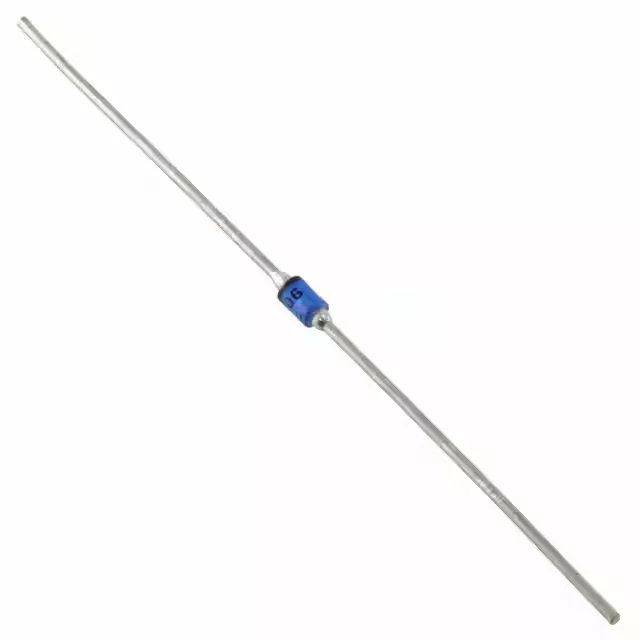
The 1N6630 comes in an A, Axial through-hole package, supplied in bulk. The axial lead form is the standard for point-to-point wiring, turret-terminal boards, and high-reliability hand-assembled power supplies where a surface-mount diode's solder-joint fatigue under thermal cycling is a concern. The through-hole body also dissipates heat through the leads into the board copper or a terminal block — the thermal path is the lead cross-section, not a pad under the body. For a rectifier in an unpressurised avionics bay or an outdoor telecom rectifier that sees -40 °C startup and 105 °C steady-state, this diode does not require derating at the cold end and has margin at the hot end.
Forward drop and leakage — the conduction and standby loss numbers
For a 1.4 A load in a 50 °C ambient, the junction rise above case is manageable with lead-length cooling; for continuous operation near the rating, the lead length and board copper area become the thermal design variables. Reverse leakage is 2 µA at 990 V — a low figure that keeps standby dissipation under 2 mW even at the full blocking voltage. This matters in a capacitor-charging circuit or a hold-up supply where the diode sits reverse-biased for long periods and the leakage current would drain the storage cap. The diode capacitance is 40 pF at 10 V reverse bias, 1 MHz. In a snubber design, this capacitance adds to the node capacitance and shifts the RC time constant — a 40 pF contribution is small relative to a typical MOSFET output capacitance but should be included in the snubber calculation for a 990 V rail.