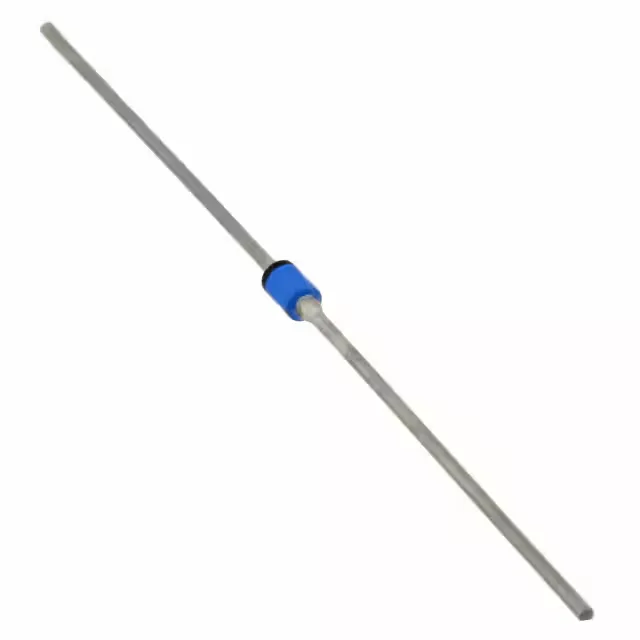
The 1N6627/TR: The 30 ns reverse recovery time qualifies this diode under the Fast Recovery classification of ≤500 ns, but the real margin is significant: 30 ns is an order of magnitude faster than the class threshold. In a 100 kHz flyback converter, that trr keeps the reverse-recovery charge low enough to avoid excessive switching losses in the primary MOSFET — the diode recovers before the drain voltage rings back up. The 40 pF junction capacitance at 10 V is a secondary factor for snubber design. At 100 kHz, the capacitive current through the junction is about 2.5 mA — negligible for the 1.75 A forward current, but worth budgeting if the diode sits across a resonant tank where the capacitance shifts the tuning.
440 V reverse and 1.75 A forward — the operating envelope
Rated for 440 V DC reverse and 1.75 A average rectified current, this diode fits secondary-side rectification in off-line power supplies up to about 250 W output, or as a freewheeling diode across a 400 V DC bus. The 2 µA reverse leakage at 440 V is low enough that self-heating from leakage is negligible at 25°C, but the leakage doubles roughly every 10°C. At 125°C junction, expect leakage around 32 µA — still acceptable for most circuits, but worth verifying if the diode blocks the full rail voltage at high ambient.
Through-hole axial — board-fit considerations
The A, Axial package with through-hole mounting is the standard leaded form factor. The body diameter is approximately 0.160 inches, lead diameter 0.025 inches — confirm the PCB hole size for a snug interference fit without stressing the glass passivation. Tape and reel packaging suits automated insertion but the axial body orientation requires a radial-tape feeder or manual hand-stuffing for low volumes.
Junction temperature range — military-grade thermal margin
The 150°C absolute maximum junction means the die can survive brief overloads during motor start or capacitor inrush without immediate failure — but continuous operation above 125°C accelerates the thermal fatigue of the solder joint between the die and the lead frame.