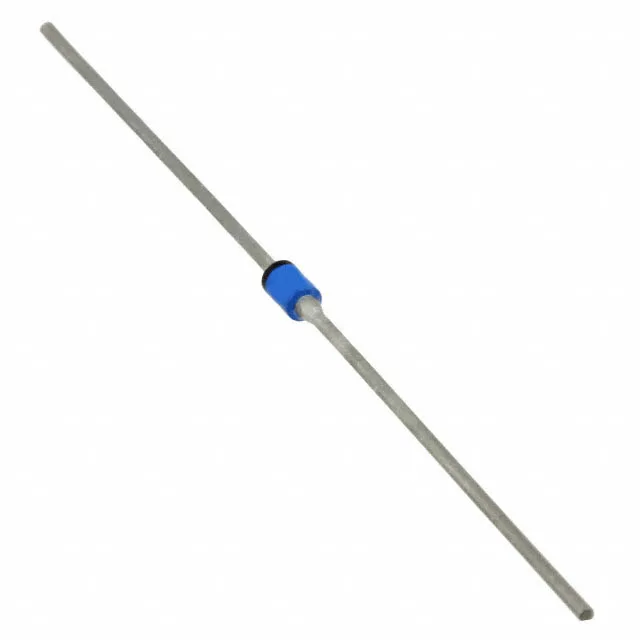
Rectifier ratings and the switching-stage fit
The 1N6620/TR: Rated 220 V DC reverse (Vr max) and 1.2 A average rectified current (Io) — this defines the rectifier's place in a 220 VDC bus or a half-wave supply rail where the peak repetitive reverse voltage stays under the 220 V ceiling. The 30 ns reverse recovery time (trr) places it firmly in the fast-recovery class (≤ 500 ns for currents above 200 mA, per the speed classification). That recovery speed governs switching losses in a 50–100 kHz PFC boost or flyback secondary; a standard-recovery part would run hotter at those frequencies. 10 pF junction capacitance at 10 V reverse bias influences the snubber design and the switching edge rate. For a 100 kHz hard-switched stage, the capacitive switching loss from this 10 pF is negligible, but the stored charge from the 30 ns trr dominates the turn-off loss budget.
Temperature grade and package reality
Junction temperature range -65 °C to +150 °C covers military/aerospace thermal cycling and high-ambient industrial enclosures. The 150 °C Tj max is the limit for the silicon die, not the solder joint — the axial-lead glass-passivated body handles the full range without derating. Supplied in A-Axial (DO-204AL equivalent) through-hole package, on Tape & Reel for automated insertion. The axial lead bend is standard for PTH board assembly; the reel format suits high-volume pick-and-place with lead-forming tooling.
Active sourcing through independent channels
No official successor or second-source cross-reference is published. The reel quantity and date code are lot-specific at RFQ.