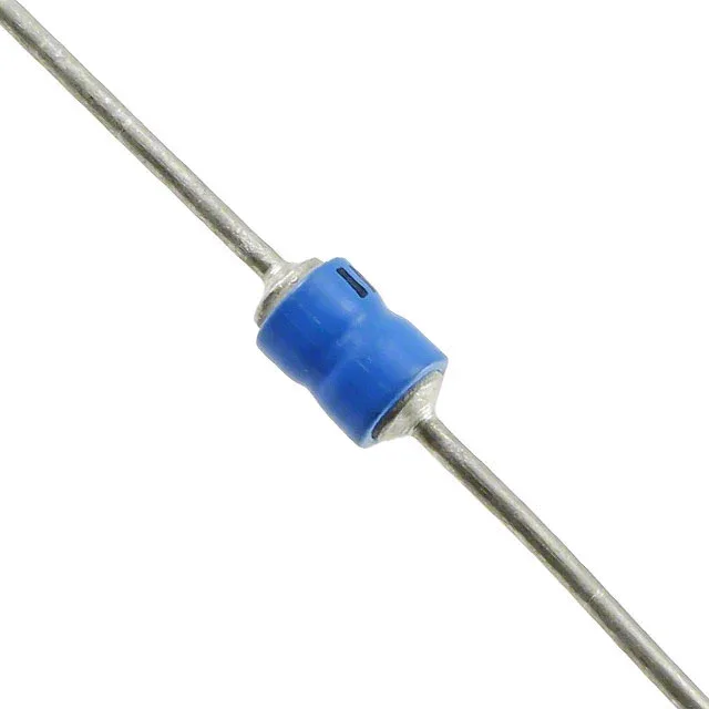
Transient protection for a 5 V rail in harsh environments
Its 5 V reverse standoff voltage means it sits across the rail without conducting during normal operation; the 5.6 V minimum breakdown is the threshold where it starts shunting current; and the 9 V maximum clamp is the peak voltage the protected load sees during a surge. The single unidirectional channel means polarity matters — cathode to the rail, anode to ground.
Clamping voltage and peak current — sizing the protection window
With a 9 V maximum clamp at the 8/20 µs waveform peak current of 315 A, the 1N6461 holds the transient below the absolute-max rating of many 5 V logic families and sensors. The 500 W peak pulse power sets the energy-handling budget for a single-event surge — derate for repetitive pulses per the datasheet impulse curve.
Active production — no lifecycle risk for BOM planning
The part is a through-hole axial device — a mature package with broad second-source availability in the TVS diode class, though no direct Microchip cross-reference is published. For an exact fit, confirm the breakdown voltage tolerance and peak pulse power against your surge requirement.
The 1N6461 is available through our distribution channel for RFQ-based pricing and lead time. Confirm the axial package and unidirectional polarity match your PCB footprint before committing.