5.6 V regulation with a 1 W thermal budget
The 1N4734PE3/TR8 is a 5.6 V Zener diode from Microchip Technology, rated for 1 W continuous power dissipation. With a ±10% tolerance, the actual Zener voltage can fall between 5.04 V and 6.16 V. For a precision reference, a tighter-tolerance part would be needed; for general clamping or crude regulation, this band is usually acceptable.
DO-41 axial package — board-fit and thermal path
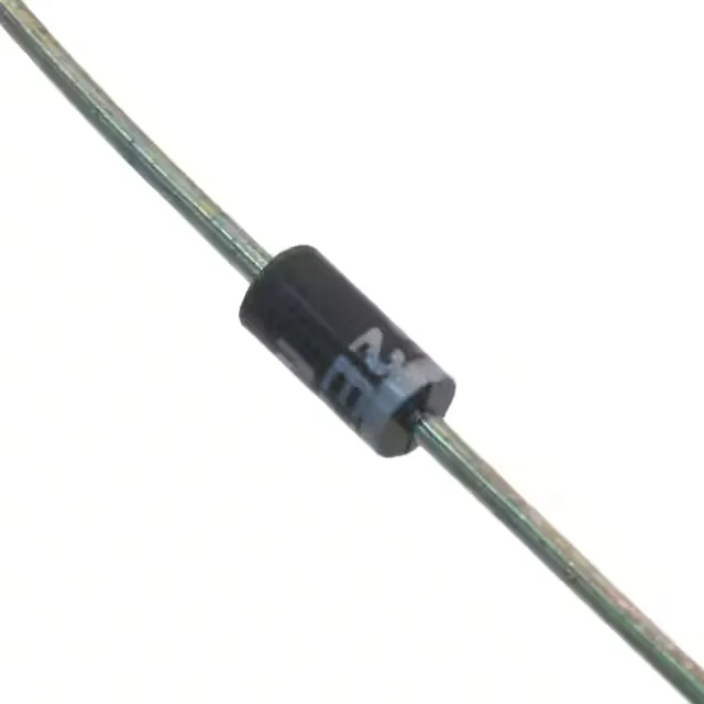
The leads are typically formed for through-hole PCB mounting or point-to-point wiring, and the body is small enough for dense layouts where a surface-mount Zener would not handle the 1 W dissipation without a large copper pad. The 1 W power rating assumes adequate lead length and ambient temperature up to 50 °C; above that, derating applies. In practice, the DO-41 package relies on the leads to conduct heat to the PCB copper, so the trace width and copper area around the anode and cathode pads directly influence the junction temperature.
Operating range and leakage behaviour
The 150°C maximum junction temperature is typical for silicon Zener diodes and sets the upper bound for the thermal design. Reverse leakage current is 10 µA maximum at 2 V reverse bias — well below the Zener voltage, so this is the leakage in the non-conducting region. At 5.6 V the leakage will be higher but still in the microamp range for most of the temperature range, which matters for battery-powered circuits where every microamp counts. The maximum Zener impedance (Zzt) is 5 Ohms at the test current. This low impedance means the voltage across the diode changes only modestly with current variations, which is the whole point of a Zener regulator: the 5.6 V rail stays within a few hundred millivolts even as the load current shifts.
Forward conduction mode
When forward-biased, the diode conducts with a maximum forward voltage of 1.2 V at 200 mA. This is typical for a silicon Zener used as a rectifier or clamp in the forward direction, though the primary application is reverse-breakdown regulation.