What the standoff and clamping ratings mean for telecom protection
The 5.0SMDJ33A clamps at 53.3 V maximum under a 93.9 A peak pulse (10/1000 µs waveform), while the reverse standoff sits at a nominal 33 V — meaning it sits passively on the line at working voltage and activates only when a transient exceeds that threshold. The 36.7 V minimum breakdown is the floor; the part triggers predictably within a narrow window rather than drifting high.
5 kW peak pulse in a telecom line-card context
5 kW peak pulse capacity at the 10/1000 µs wave shape is the standard telecom surge stress profile — it covers the residual lightning surge that gets through the primary protection stage on a copper line card. The 93.9 A peak current rating tells you the let-through current the downstream ASIC sees during the clamp event, so the clamping voltage figure is what drives the downstream IC transient-withstand margin.
DO-214AB SMC — reel packaging and assembly fit
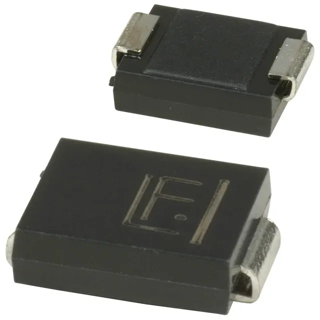
CT is useful for prototypes or low-quantity board spins. The SMC (DO-214AB) footprint is a common telecom pinout, but verify the cathode band orientation against your layout — the band marks the cathode and defines the unidirectional polarity direction.
For telecom OEMs running multi-year product cycles, this means a long supported lifecycle — the 5.0SMDJ series is a core Littelfuse line and not a specialty build.