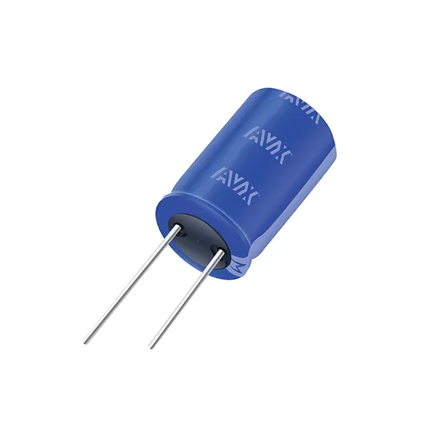
600 F at 2.7 V — sizing the energy buffer
The SCCY85B607SLBLE: 600 F at 2.7 V stores roughly 2.2 kJ of usable energy (E = ½ C V²). That is enough to ride through a 100 ms mains dropout at 22 kW, or to power a 10 A load at 5 V for several seconds through a boost converter. The 1.6 mOhm ESR sets the I²R heating during charge/discharge — at a 100 A pulse the internal dissipation is 16 W, so the thermal path to the chassis mount matters. The -10% to +30% capacitance tolerance means the actual part can measure from 540 F to 780 F. In a series stack for higher voltage, the +30% upper bound drives the balancing resistor design — the cell with the highest capacitance sees the lowest voltage share during charging.
Chassis mount with weld stud — mechanical and electrical integration
This is a radial can, 35 mm diameter by 87 mm seated height, terminated with weld studs for chassis mounting. It does not go through a reflow oven — the weld studs are designed for bolted or welded bus-bar connections in a power assembly, not for a PCB footprint. The bulk packaging (loose in a box) matches the manual handling expected for this form factor.
Lifetime and temperature — 1000 hours at 60°C
The rated lifetime is 1000 hours at 60°C, which is the accelerated test condition per the SCC LE series specification. Operating at 40°C instead of 60°C approximately doubles the life per the Arrhenius rule of thumb for electrolytic capacitors, so the practical service life in a 40°C enclosure is several thousand hours.