600 V CoolMOS — the switching loss trade-off you need to budget for
Rds(on) and gate drive — 10 V is mandatory for rated performance
Below that, the on-resistance climbs steeply. The gate threshold is 3.9 V max at 350 µA, but the part is not characterised for 5 V logic-level drive — a dedicated gate driver or bootstrap rail is needed. Input capacitance is 790 pF at 25 V Vds, which together with the 27 nC gate charge sets the switching speed. A gate resistor in the 10–22 Ohm range gives a clean turn-on without excessive ringing on a typical 600 V bus.
Through-hole TO-262 — rework-friendly, but watch the tab
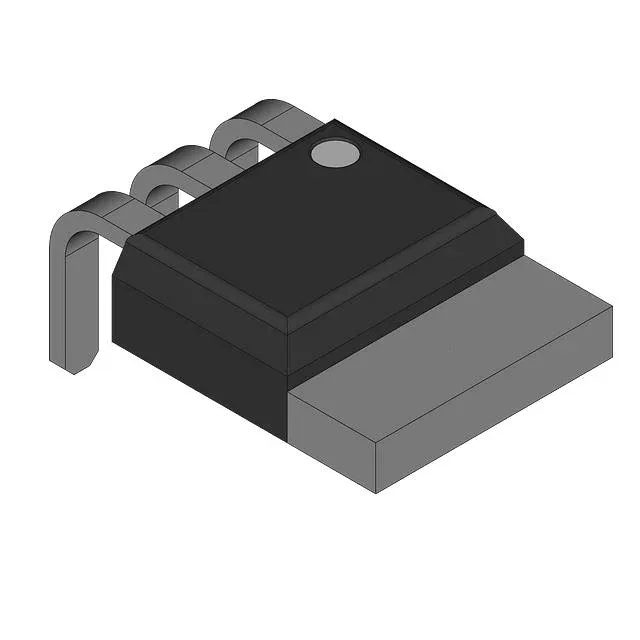
The TO-262-3 (I²Pak) package is a through-hole variant of the D²Pak, with long leads that suit board-level rework. With 83 W max power dissipation at case temperature, the tab-to-ambient thermal path is the limiting factor; a 1-inch-square copper pad on a 2 oz board is a reasonable starting point. No moisture sensitivity level concern for a through-hole part, but the leads are tin-plated — confirm solder profile compatibility with your assembly house.