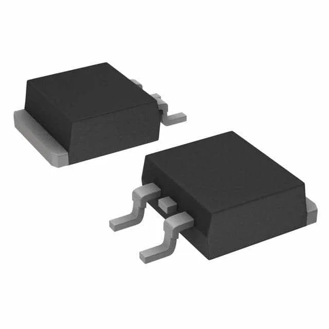
600 V NPT IGBT in a D²Pak — what it brings to the power stage
The NPT structure gives a positive temperature coefficient on Vce(sat), so paralleling multiple devices shares current without hot-spot runaway — a real advantage in a 400 VDC-bus PFC or motor-drive output stage where you might need two or three in parallel to hit the load current.
31 A continuous, 62 A pulsed — derating matters at 150°C junction
Continuous collector rating is 31 A, with a 62 A pulsed capability. The junction temperature range stretches from -55°C to 150°C, so the 31 A number applies at a 25°C case temperature — expect the usable current to drop as the die heats up. The 139 W max power dissipation gives a rough ceiling for the heatsink design; the actual safe operating area depends on the case temperature and the switching frequency you run. Switching energy is 570 µJ under the test condition of 400 V, 15 A, 21 Ohm gate resistor, 15 V gate drive. That 570 µJ per pulse, multiplied by the switching frequency, sets the switching loss component of the total dissipation. The 76 nC total gate charge tells the driver what current it needs to push to hit your target rise time.
Switching speed and reverse recovery
Turn-on delay is 32 ns, turn-off delay 234 ns at 25°C. The 279 ns reverse recovery time belongs to the internal co-pack diode — relevant if you are using the IGBT in a half-bridge leg where the diode conducts the freewheel current. The 2.4 V typical Vce(sat) at 15 V gate, 15 A collector is the conduction voltage drop that multiplies with the duty cycle to give the conduction loss.