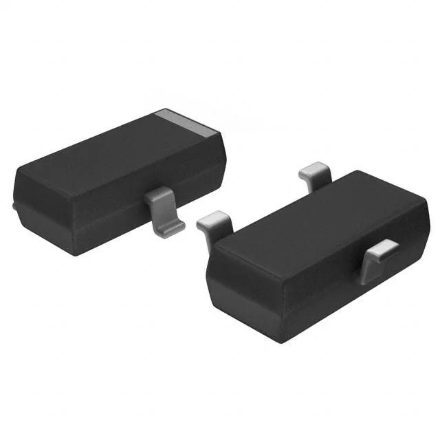
P-channel load switch in a SOT-23
The ISS17EP06LMXTSA1: It comes in a PG-SOT23-3 package, a compact footprint for board-level load switching, battery protection, or high-side level translation where the supply rail is 12 V or 24 V.
On-resistance and drive voltage — what 1.7 Ohm means at the rail
Plan for a 5 V or 10 V gate signal if the application needs the rated 300 mA throughput without excessive voltage drop. Gate charge is 1.79 nC at 10 V, a light load for any microcontroller GPIO or small-signal driver. Input capacitance is 55 pF at 30 V Vds, which keeps the switching edge rates fast enough for low-frequency PWM or on/off control without a dedicated gate resistor.
Thermal envelope in a SOT-23
Maximum power dissipation is 360 mW at 25 °C ambient, derated to zero at 150 °C junction. The SOT-23-3 package has no exposed pad; the drain is pin 2, and the copper area on the PCB under the part sets the effective thermal resistance. For continuous 300 mA through a 1.7 Ohm channel, the I²R loss is about 150 mW — within the budget at room temperature, but above 85 °C ambient the margin shrinks.