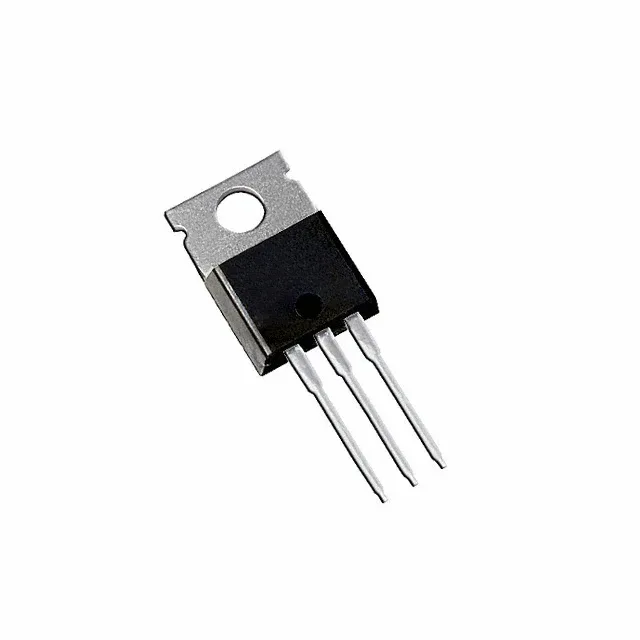
The logic-level gate threshold (2 V max at 250 µA) lets a 5 V microcontroller or FPGA drive it directly through a gate resistor — no separate driver IC needed for moderate switching frequencies.
On-resistance and gate charge — sizing the driver and the thermal budget
At 47 A the conduction loss is I²R = 47² × 0.022 ≈ 48.6 W — well within the 110 W case-temperature power dissipation rating, but the junction-to-case thermal path demands a heatsink with adequate surface area and airflow. The total gate charge of 48 nC at 5 V means a 5 V gate driver sourcing 1 A can switch the gate in about 48 ns; a 100 mA source stretches it to 480 ns. Match the drive current to the target switching frequency to keep switching losses under control.
Temperature range and package — where this TO-220AB fits
The TO-220AB through-hole package — three leads, metal tab — bolts directly to a chassis or heatsink with a single M3 screw. The exposed drain tab is electrically live; an insulating pad or thermal compound is needed if the heatsink is grounded.