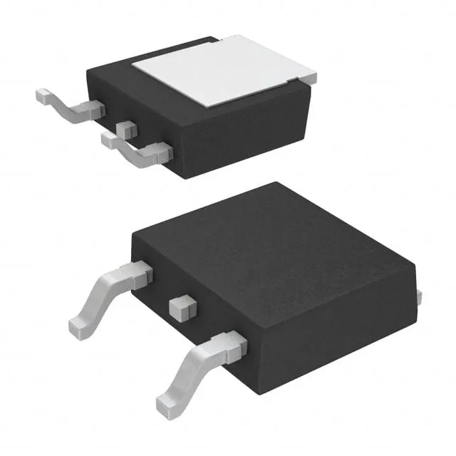
Infineon Technologies IRLR7833TRPBF

IRLR7833TRPBF MOSFET N-CH 30V 140A DPAK, 4.5mOhm

MPNIRLR7833TRPBF
End of Life

Infineon HEXFET® IRLR7833TRPBF, N-Channel MOSFET, 30V Vdss, 140A Id, 4.5mOhm Rds(on) at 10V, DPAK (TO-252) surface mount, -55°C to 175°C.

$1.36Ref. price · indicative, final on quote
PackagingTO-252-3, DPak (2 Leads + Tab), SC-63
RoHSROHS3 Compliant
SeriesHEXFET®
Independent supplier — new & surplus stockAuthenticity-screened · ESD-safe packingListing updated Jul 2026

Specifications

IRLR7833TRPBF specifications
ParameterValue
SeriesHEXFET®
FET typeN-Channel
MountingSurface Mount
Drain to source voltage30 V
Drive voltage (Max rds on, min rds on)4.5V, 10V
Current - continuous drain (Id) @ 25°C140A (Tc)
Power dissipation140W (Tc)
Operating temperature-55°C ~ 175°C (TJ)
PackageTape & Reel (TR); Cut Tape (CT)
Vgs±20V
TechnologyMOSFET (Metal Oxide)
CaseTO-252-3, DPak (2 Leads + Tab), SC-63
Vgs(th) (Max) @ id2.3V @ 250µA
Rds on (Max) @ id, vgs4.5mOhm @ 15A, 10V
Gate charge (Qg) (Max) @ vgs50 nC @ 4.5 V
Input capacitance (Ciss) (Max) @ vds4010 pF @ 15 V

Product details

At 15A drain current and 10V gate drive, the maximum on-resistance is 4.5 mOhm.

The 4010 pF input capacitance at 15V Vds is typical for this current class; the gate-drive loop should be kept tight to avoid ringing. The DPAK footprint is shared with many TO-252 MOSFETs, so a layout validated for one often accepts this part with minor pad adjustments.

Frequently asked questions

What is the difference between IRLR7833TRPBF and IRLR7833PBF?

The two parts are electrically identical — same die, same ratings. The difference is packaging: IRLR7833TRPBF ships in Tape & Reel, while IRLR7833PBF ships in Tube (bulk). Choose the reel variant for automated pick-and-place assembly.

Can I use IRLR7833TRPBF for 12V motor control?

Yes. The 30V Vdss provides headroom above a 12V bus for inductive flyback. The 4.5 mOhm Rds(on) at 10V gate drive keeps conduction losses low, and the 140A continuous rating far exceeds typical motor-start surge currents. Ensure the gate driver can supply the 50 nC gate charge at the switching frequency.