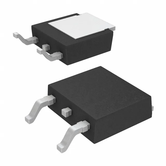
100 V, 17 A N-channel — the switching envelope
Maximum on-resistance is 105 mOhm at 10 A gate drive of 10 V — the Rds(on) floor for conduction-loss calculations in a switching regulator or load switch. That keeps the drive current modest — a 34 nC gate switched at 100 kHz draws about 3.4 mA from the gate driver, well within a standard totem-pole driver's capability.
Housed in a TO-252-3 D-Pak (2 leads plus tab), this is a surface-mount power package with an exposed drain tab. On a standard 1 oz copper pad with adequate via stitching, the 79 W maximum dissipation at case temperature is achievable; without the copper plane, derate aggressively. The D-Pak is hand-solderable with a standard iron if the tab gets a preheat bump — no hot-air station required for a field swap. Orientation is obvious: the tab is drain, gate is pin 1 (left when the tab faces away), source is pin 2. Marking on the package body is legible under magnification.
No official successor or second-source cross-reference is listed in the manufacturer documentation.
The 175°C ceiling gives headroom for transient overloads without immediate derating to a lower-temperature device.