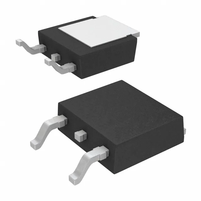
Infineon Technologies IRLR120NTRPBF

IRLR120NTRPBF HEXFET N-Ch MOSFET, 100V 10A DPAK

MPNIRLR120NTRPBF
End of Life

Infineon HEXFET® IRLR120NTRPBF, N-Channel MOSFET, 100 V Vdss, 10 A Id, 185 mOhm Rds(on) at 10 V, D-Pak (TO-252) surface mount, -55°C to 175°C.

$1.0Ref. price · indicative, final on quote
PackagingTO-252-3, DPak (2 Leads + Tab), SC-63
StockContact for availability
MOQ1 pcs
  • 100% new & originalTraceable channels only — no refurbs, no pulls, no remarked parts.
  • Date & lot codes on quoteStated per line before you commit; label photos on request.
  • MSL-compliant ESD packingMoisture-sealed bags with indicator cards; reels photo-verified.
  • PayPal buyer protectionPay by T/T, PayPal or Payoneer — card payments covered end to end.

Specifications

IRLR120NTRPBF Technical Specifications
ParameterValue
SeriesHEXFET®
FET typeN-Channel
Mounting typeSurface Mount
Drain to source voltage100 V
Drive voltage (Max rds on, min rds on)4V, 10V
Current - continuous drain (Id) @ 25°C10A (Tc)
Power dissipation48W (Tc)
Operating temperature-55°C ~ 175°C (TJ)
PackageTape & Reel (TR); Cut Tape (CT)
Vgs±16V
TechnologyMOSFET (Metal Oxide)
CaseTO-252-3, DPak (2 Leads + Tab), SC-63
Vgs(th) (Max) @ id2V @ 250µA
Rds on (Max) @ id, vgs185mOhm @ 6A, 10V
Gate charge (Qg) (Max) @ vgs20 nC @ 5 V
Input capacitance (Ciss) (Max) @ vds440 pF @ 25 V

Product details

100 V N-channel HEXFET in a rework-friendly DPAK

The Infineon IRLR120NTRPBF is a 100 V, 10 A N-channel power MOSFET from the HEXFET series, built on a standard metal-oxide trench process. The DPAK (TO-252) package is a surface-mount tabbed outline — the exposed drain tab solders to the board copper for heat spreading, and the three-lead body reworks cleanly under hot air if you preheat the board to 100°C.

Rds(on) is specified at 185 mOhm maximum with 10 V on the gate and 6 A drain current. The 2 V maximum threshold at 250 µA means the device starts conducting early, but full enhancement requires the higher drive voltage to minimise conduction loss. Gate charge is 20 nC at 5 V — a modest figure that keeps switching losses low in the 10–50 kHz range. The 440 pF input capacitance at 25 V drain bias gives the driver a clear capacitive load to push; a 1 A gate driver charges the gate in about 20 ns, so rise-time-limited switching above 100 kHz is not the target application for this part.

Temperature range and thermal budget

The 48 W maximum power dissipation at the case is a theoretical ceiling; real-world dissipation is set by the PCB copper area under the tab and the airflow across the board.

Sourcing and lifecycle posture

It is ROHS3 compliant and available through independent distribution.

Frequently asked questions

What is the Rds(on) of the IRLR120NTRPBF at 10V?

The maximum on-resistance is 185 mOhm at 10 V gate drive with 6 A drain current. This is the conduction loss figure used for thermal design in load-switch and low-frequency PWM applications.

How does the IRLR120NTRPBF compare to the IPD50R950CEAUMA1?

The IPD50R950CEAUMA1 is a 500 V CoolMOS device with 950 mOhm Rds(on) and 4.3 A current rating — it targets high-voltage flyback and PFC stages, not the 100 V load-switch or low-voltage DC-DC space the IRLR120NTRPBF serves. The 100 V rating and 10 A continuous current of the IRLR120NTRPBF make it a better fit for 48 V bus, automotive auxiliary loads, and industrial solenoid drives.