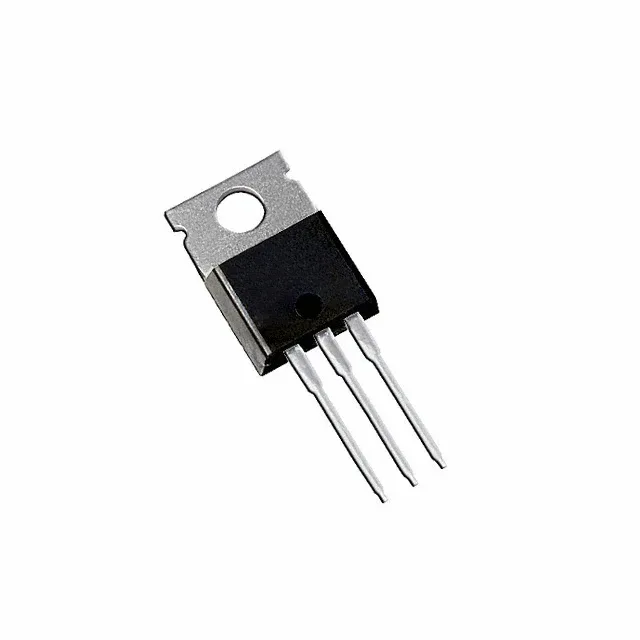
Infineon Technologies IRL1404ZPBF

IRL1404ZPBF MOSFET, N-Ch 40V 75A TO-220AB, 3.1mOhm Rds(on)

MPNIRL1404ZPBF
End of Life

Infineon IRL1404ZPBF, HEXFET® series, N-channel MOSFET, 40 V Vdss, 75 A continuous drain, 3.1 mOhm Rds(on) at 10 V, logic-level gate, TO-220AB through-hole, -55 to 175 °C junction.

$2.9Ref. price · indicative, final on quote
PackagingTO-220-3
StockContact for availability
MOQ1 pcs
  • 100% new & originalTraceable channels only — no refurbs, no pulls, no remarked parts.
  • Date & lot codes on quoteStated per line before you commit; label photos on request.
  • MSL-compliant ESD packingMoisture-sealed bags with indicator cards; reels photo-verified.
  • PayPal buyer protectionPay by T/T, PayPal or Payoneer — card payments covered end to end.

Specifications

IRL1404ZPBF Technical Specifications
ParameterValue
SeriesHEXFET®
FET typeN-Channel
Mounting typeThrough Hole
Drain to source voltage40 V
Drive voltage (Max rds on, min rds on)4.5V, 10V
Current - continuous drain (Id) @ 25°C75A (Tc)
Power dissipation230W (Tc)
Operating temperature-55°C ~ 175°C (TJ)
PackageTube
Vgs±16V
TechnologyMOSFET (Metal Oxide)
CaseTO-220-3
Vgs(th) (Max) @ id2.7V @ 250µA
Rds on (Max) @ id, vgs3.1mOhm @ 75A, 10V
Gate charge (Qg) (Max) @ vgs110 nC @ 5 V
Input capacitance (Ciss) (Max) @ vds5080 pF @ 25 V

Product details

3.1 mOhm at 75 A — the conduction loss floor

The IRL1404ZPBF is an Infineon HEXFET N-channel MOSFET rated 40 V drain-source and 75 A continuous drain at 25 °C case temperature. The headline spec is the 3.1 mOhm maximum on-resistance at Vgs=10 V and Id=75 A — at full load the I²R loss is under 18 W, which keeps the junction within the 175 °C ceiling with a moderate heatsink. The logic-level gate threshold of 2.7 V max at 250 µA means a 5 V or 3.3 V MCU output can turn it on hard, though the datasheet recommends 4.5 V drive for the lowest Rds(on).

175 °C junction — where this 40 V FET goes

The operating junction range spans -55 to 175 °C, which is wider than the typical 150 °C ceiling for logic-level FETs. That 25 °C headroom matters in under-hood automotive, industrial motor-drive enclosures, and downhole instrumentation where ambient air hits 125 °C and the junction needs room to breathe under ripple current. The TO-220AB package with the metal tab solders to a PCB copper plane or bolts to a chassis heatsink — the 230 W power dissipation rating assumes the tab is held at 25 °C.

110 nC gate charge — sizing the driver

Total gate charge at 5 V is 110 nC. For a 100 kHz switching regulator, that translates to 11 mA of average gate-drive current — well within a standard half-bridge driver IC. The input capacitance of 5080 pF at 25 V drain-source sets the Miller plateau width; a gate resistor in the 10–22 Ω range keeps the switching edge under control without excessive ringing. Through-hole mounting in the TO-220-3 footprint means the gate-drive loop can be kept tight with a local resistor and Schottky catch diode soldered directly to the leads.

Frequently asked questions

What is the Rds(on) of IRL1404ZPBF?

3.1 mOhm maximum at Vgs=10 V and Id=75 A. At 4.5 V drive the on-resistance is higher but still well below 5 mOhm — the exact value is in the datasheet output characteristic curve.

Can IRL1404ZPBF be used as a replacement for IRF1404?

The IRL1404ZPBF is a logic-level gate variant of the IRF1404 family. Both are 40 V N-channel FETs in TO-220AB, but the IRL1404ZPBF has a lower gate threshold (2.7 V vs ~4 V) and a lower Rds(on) at 10 V. It is a drop-in replacement in most circuits, but confirm the gate-drive voltage — the IRF1404 needs 10 V to saturate, while the IRL1404ZPBF saturates at 4.5 V.