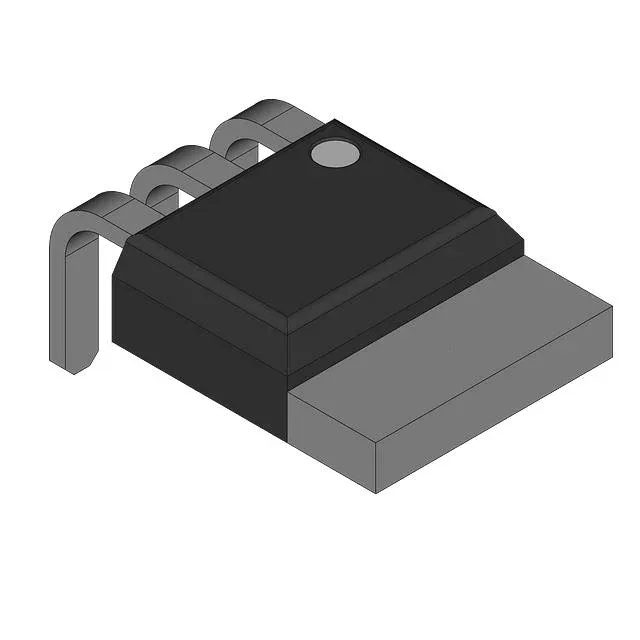
600 V NPT IGBT in a TO-262 — motor-drive and PFC workhorse
The IRGSL15B60KDPBF-INF: The NPT structure gives a positive temperature coefficient on Vce(on), which simplifies paralleling — each die shares current naturally as it warms up.
Switching losses at 400 V, 15 A, 22 Ω gate resistor
Under the test condition of 400 V, 15 A, 22 Ω gate drive, and 15 V gate bias, the turn-on energy is 220 µJ and turn-off energy is 340 µJ. The corresponding delay times are 34 ns on and 184 ns off at 25 °C. These numbers let you estimate the switching-loss contribution to the junction temperature rise at your operating frequency — at 20 kHz hard-switched, the per-device switching loss alone runs about 11 W before accounting for conduction.
Conduction voltage and gate charge
The total gate charge is 56 nC.
The TO-262 package has long leads (I²Pak format) for through-hole mounting; the exposed copper tab on the back side must be soldered or clamped to a heatsink for thermal management.