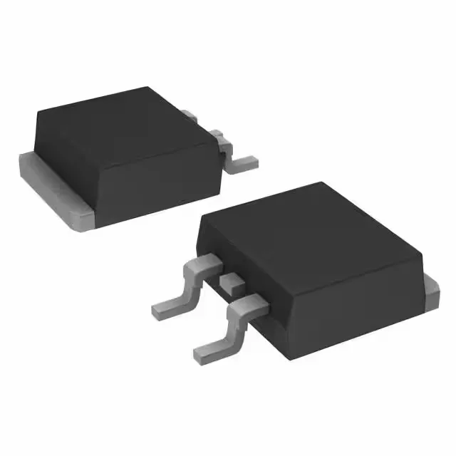
Infineon Technologies IRFZ44NSPBF — Discrete Semiconductors

IRFZ44NSPBF N-Channel MOSFET, 55V 49A HEXFET, D2PAK

MPNIRFZ44NSPBF
End of Life

Infineon HEXFET® N-Channel MOSFET, IRFZ44NSPBF, 55 V drain-source, 49 A continuous drain at 25°C case, 17.5 mOhm max Rds(on) at 10 V gate drive, 63 nC gate charge, D2PAK (TO-263) surface-mount package, -55°C to 175°C junction temperature.

$1.8400Ref. price · indicative, final on quote
Independent supplier — new & surplus stockAuthenticity-screened · ESD-safe packingListing updated Aug 2026

Specifications

IRFZ44NSPBF specifications
ParameterValue
SeriesHEXFET®
FET typeN-Channel
MountingSurface Mount
Drain to source voltage55 V
Drive voltage (Max rds on, min rds on)10V
Current - continuous drain (Id) @ 25°C49A (Tc)
Power dissipation3.8W (Ta), 94W (Tc)
Operating temperature-55°C~175°C(TJ)
PackageTube
Vgs±20V
TechnologyMOSFET (Metal Oxide)
CaseTO-263-3, D²Pak (2 Leads + Tab), TO-263AB
Vgs(th) (Max) @ id4V @ 250µA
Rds on (Max) @ id, vgs17.5mOhm @ 25A, 10V
Gate charge (Qg) (Max) @ vgs63 nC @ 10 V
Input capacitance (Ciss) (Max) @ vds1470 pF @ 25 V

Product details

55 V, 49 A, 17.5 mOhm — the switching sweet spot

The IRFZ44NSPBF is an N-channel enhancement-mode MOSFET from Infineon's HEXFET series, built on planar stripe technology. The D2PAK (TO-263) surface-mount package suits automated assembly on power-ground planes with a thermal pad for heatsinking.

Gate charge and switching losses

With a maximum gate charge of 63 nC at 10 V drive, this part falls in the moderate-charge class for a 49 A FET. For a 100 kHz switching frequency, the gate-drive power loss is roughly Qg × Vgs × fsw = 63 nC × 10 V × 100 kHz = 63 mW, which is manageable with a standard gate-driver IC. The input capacitance of 1470 pF at 25 V drain-source gives a rough idea of the switching speed — expect turn-on and turn-off delays in the tens of nanoseconds with a 10 Ω gate resistor.

Temperature range and thermal management

The maximum power dissipation is 3.8 W at 25°C ambient (still air) and 94 W at 25°C case temperature. The 94 W figure assumes the case is held at 25°C via a heatsink; in practice, a TO-263 on a 1 oz copper pad on a 2-layer board will dissipate roughly 2–3 W before the junction hits 175°C in free air. For continuous 49 A, a substantial heatsink or forced airflow is mandatory — the junction-to-case thermal resistance is not listed here, but the 94 W rating at Tc = 25°C implies roughly 1.6°C/W junction-to-case.

Supplied in a D2PAK (TO-263-3, 2 leads plus tab) surface-mount package. The gate threshold voltage is 4 V maximum at 250 µA drain current, so logic-level drive at 3.3 V will not fully enhance the channel — a 5 V or 10 V gate drive is required for rated Rds(on).

This means no last-time-buy risk for new designs, and the usual supply-channel availability through independent distribution. The part is RoHS-compliant as indicated by the 'SPBF' suffix (lead-free plating).

Frequently asked questions

Can I use IRFZ44NSPBF as a replacement for IRFZ44N?

The IRFZ44N is a through-hole TO-220 package, while the IRFZ44NSPBF is a surface-mount D2PAK (TO-263). They share the same die and electrical ratings (55 V, 49 A, 17.5 mOhm), so the IRFZ44NSPBF can replace the IRFZ44N in a design if the PCB footprint is changed to accommodate the D2PAK land pattern. The gate charge and switching characteristics are identical.

What is the gate charge of IRFZ44NSPBF?

The maximum gate charge is 63 nC at 10 V gate-source voltage.

What is the Rds(on) of IRFZ44NSPBF?

The maximum on-resistance is 17.5 milliohms at 25 A drain current and 10 V gate drive.

What package is IRFZ44NSPBF?

It comes in a D2PAK (TO-263-3) surface-mount package, also referred to as D²Pak (2 leads plus tab).

Is IRFZ44NSPBF RoHS compliant?

Yes, the 'SPBF' suffix indicates lead-free (RoHS-compliant) plating.